Close
0%
0%

Vacuum fluorescent display (VFD) hacks

Exploring a couple of alternative uses for vacuum fluorescent displays (VFDs)

Similar projects worth following
Vacuum fluorescent displays (VFDs) are triode vacuum tubes intended to be used as character displays. N9WOS was the first to demonstrate that a VFD can also be used as an amplifying device (back in 2005). The appeal of VFD for amplification seems to be that it can be operated at low anode voltage (20V, or even lower). However, this is only possible with positive grid bias, and both gain and signal quality suffer. I want to try using VFDs for amplification with an operating point with negative grid, as $DEITY intended. I might also try to use a VFD as a voltage-controlled resistor.

The day job of vacuum fluorescent displays is to be character displays. Until OLEDs became price competitive, VFDs had the unique ability of being bright enough to be read in full sunlight. I'm trying to educate myself about the practicality of using VFDs for a couple of side gigs, like signal amplification, signal mixing and as voltage-controlled resistors. There are several documented uses of VFDs for amplification, but I have unanswered question. What is the operating point? What gain do you get? Isn't the distortion unpleasant with a positive grid bias? How do you deal with the high output impedance? This project is where I will tinker to find answers, and hopefully be disciplined enough to post some useful details and quantitative results.

Spoiler alert: I think I'm already gravitating toward a conventional triode operating point with negative grid bias. This will inevitably require a relatively high anode voltage. But as ancient oriental wisdom teaches us: "If it doesn't spark joy in your life, you have to crank up the voltage".

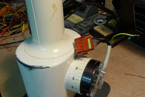
The VFD on my KitchenAid gas range doing its day job:

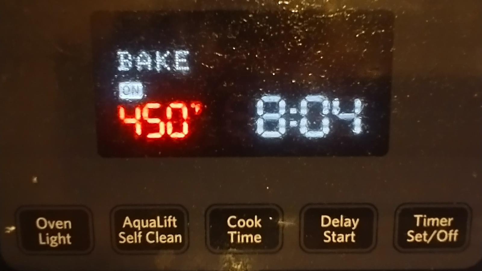
It appreciates the steady pay check and the health insurance, but daydreams of being a guitar preamp and hooking up with a power beam tetrode...

  • 1 × Futaba 20-SD-06GK VFD A 20-character VFD (with 20 grids and 35 anode segments), $5 on EBay
  • 1 × HVAC-control transformer
  • 1 × Small transformer (8 VA, 120 to 9 or 10 V) Power supplies for answering machines and modems are a good source for these
  • 1 × Reservoir cap (2.2 mF, 200 V)
  • 2 × Bridge rectifier

  • Power transformer for VFD guitar amp

    Johan Carlsson03/19/2022 at 15:43 0 comments

    I'm thinking about using the Futaba VFD as the preamp for a tiny (2W or so) guitar amp. Guitar-amp power transformers have secondaries for both high voltage (for the tube anodes) and low voltage (for filaments). Convenient, but seems like overkill for the feeble needs of this project, so I dug into my transformer stash. There, Hammond Schmammond:

    To the left is an HVAC-control transformer that will provide isolation and lowish voltage. To the right is what looks like an answering-machine power supply. Let's crack it open:

    Except for some rust and glue on the core, and copper peeking through the insulation on the mains-voltage wires, this transformer is fit for duty. So here's the configuration I have in mind:

    From left to right. Meet Shiny (HVAC-control transformer) and Rusty (the answering-machine transformer). Put mains voltage (120 Vrms) across Shiny's 208 V primary (white and red wires) to get about 14 V across the secondary (blue and yellow, Slava Ukraini). This isolated low-voltage AC will be rectified and regulated to provide clean DC for the filaments. It will also be used to as input to Rusty's low-voltage coil. If all goes well, we should then get about 170 Vrms across Rusty's high-voltage coil that we can rectify and regulate and use for B+.

    The parts on my bench, lashed up and ready for testing:

    No regulation yet, Rusty's AC output is converted to ugly DC (with significant hum) using just a bridge rectifier and a reservoir cap (2.2 mF, 200 V). Here's the DC output voltage vs. load current:

    For the preferred operating point (OP1) we want 157 V of clean (regulated) DC. I reckon we'll need ugly DC of about 170 V (the yellow box in the plot) into the voltage regulator. That makes the power budget a bit tight (2 - 2.5 W). For the alternative operating point (OP2, marked by red box), about 155 V of ugly DC should do, increasing the power budget to a comfortable 4 W.

    One more watt would have been nice, but I think Shiny and Rusty will have to do.

  • Performance of the Futaba VFD as a triode

    Johan Carlsson02/23/2022 at 19:28 0 comments

    I found the pins on the Futaba 20-SD-06GK VFD to only reluctantly accept solder so I ended up using my harshest flux (for stainless steel), and lots of it. I did wash off the flux residue with alcohol, but when I later added the battery holder (for neutralizing the luminance slant), I inadvertently left some flux. With a 140 V potential difference between two adjacent pins (a4,5 and g1), the flux residue became a conductor and the ohmic heating was enough to leave a scorch mark (and release some Magic Smoke):

    However, after another alcohol wash, the device was functional. The lesson learned is that VFDs are not made for operation at the anode voltages necessary with a negative grid bias, so special precautions need to be taken. Liquid electrical tape where the grid is closest to the anode would probably be a good idea.

    I hooked the VFD triode up to two power supplies (one for anode voltage Vak and the other for grid bias Vgk), in addition to the filament PS. Here are the anode currents Ia measured by a multimeter:

    I've identified two possible operating points (OP1 and OP2, respectively). My preferred option would be OP1, which has voltage gain A = 11 (+21dB) and anode resistance ra = 400 kΩ (estimates from eyeballing the characteristic above). As for all VFDs, the output impedance is high, about 270 kΩ. You'll need a PS capable of producing very clean DC at relatively high voltage: B+ = 157 V. The anode dissipation is Pa = 2.2 mW, which would be trivial for a conventional triode, but might be a bit high for a VFD. The fallback operating point OP2 has A = 10 (+20dB), ra= 1400 kΩ (resulting in an output impedance of 720 kΩ), B+ = 142 V and Pa = 0.6 mW.

    A surprising (at least to me) and tantalizing fact is that gain around OP1 drops fairly symmetrically for higher and lower grid bias. For a guitar preamp the resulting soft and symmetric clipping is associated with "tubey" guitar tone. You would need the signal to have Vpp close to 1 V for this "euphonic distortion" to kick in though.

    The results so far are thus encouraging enough for me to continue my VFD shenanigans: a gain of +20dB seems very achievable, the output impedance is high, but manageable and you might even get some pleasant coloring as an added bonus!

  • Multi-character VFD triode without luminance slant

    Johan Carlsson02/23/2022 at 02:42 0 comments

    One of several problems with using a multi-character VFD as a triode is that the potential across the directly heated cathode varies linearly. For my Futaba VFD the cathode voltage Vk increases from 0 V to 3.1 V from one end of the filament to the opposite end. If you simply connect the grid pins to merge the grid segments into a single grid, the grid bias Vgk will then vary by 3.1 V from one end of the grid (the g1 segment) to the other (the g20 segment). This has a very visible effect known as "luminance slant", where the characters are brighter closer to the grounded side of the filament. Luminance slant must have a deleterious effect on triode performance (reduced gain, increased distortion, increased anode resistance and output impedance), so here's my crude attempt to avoid it:

    I've connected the grid segments with a 1 kΩ resistor between each segment. I've then soldered the leads of a double-AA battery holder to pins g1 and g20, respectively, so that I can apply 3.1 V across the distributed grid to match the voltage across the filament. This will only work for operation with a negative grid! With a positive grid you get some odd currents flowing from the grid segments to the filament.

    The anode segments are merged together into a single anode by simply connecting all the pins:

    The blue-and-white wire connects the upper and lower halves of the anode.

    Time to light her up to see if the luminance slant is cured:

    Yup, that did it! The leftmost anode is a bright as the rightmost one, which is grounded. The most prominent luminance non-uniformity is now vertical instead of horizontal. The anode segments in the vertical middle (between filaments) as visibly dimmer, but I'm going to tolerate that, for now.

    Today is Twosday and I've made two posts to this project. That seems appropriate.

  • Mapping the pins on the Futaba VFD

    Johan Carlsson02/22/2022 at 04:41 0 comments

    Okiday, Futaba 20-SD-06GK VFD on the workbench with the filament heated. Fiftynine pins and no datasheet. The two outermost pins on each side were for the filament. The tube has 20 grid segments (one for each character) and 35 anode segments (5x7 phosphor pixels). So of the remaining 55 pins 20 should be for grid biasing and 35 for anode segments.

    My standard protocol for VFD pin probing is to use a small (1.3 Ah) lead-acid 12 V battery. Connect the negative terminal to the filament ground pin and connect two alligator leads to the battery positive terminal. If one alligator clip touches a grid pin and the other touches an anode pin, the phosphor on the anode segment should light up faintly. VFDs are made to operate with very positive grid bias, often with Vgk=Vak ≈ 20 V, so 12 V should be close enough. A higher voltage would be less forgiving if you accidentally touch the filament pin.

    However, in the photo below the grid pin (g15) is connected to positive filament voltage (3.1 V) and the anode pin (a1,2) is connected to a power supply.

    The voltage on the surrounding grid pins is floating, and apparently high enough to let some electrons through. The filament wires look light gray in this photo, but were dull orange to the naked eye.

    The intended use is to multiplex the shared anode segments by pulling one grid pin high at a time and to loop though grids 1 through 20 fast enough that persistence of vision makes it look like all 20 characters are continuously lit.

    For the Futaba 20-SD-06GK VFD, from left to right, pins 3-17 are a5,1 to a7,5 (row major), pins 18-37 are g1 to g20, and pins 38-57 are a1,1 to a4,5.

    The low-voltage probing (at 12 V) works well enough for me to use it even when I do have a datasheet for a VFD.

  • Futaba filament power supply

    Johan Carlsson02/22/2022 at 01:39 0 comments

    The first VFD I'm playing with is a Futaba 20-SD-06GK, which has 59 pins and I can't find a datasheet for it! I measured resistance between pins and found that pins 1 and 2 are shorted together, and so are 58 and 59. The cold resistance between the pairs is 18 Ohms, about what you'd expect for the filament. In a dark room, I crank up the voltage over the filament until the incandescence makes it barely visible. That happened at 3.1 V (47 mA).

    Like every other VFD I've seen, this one has a directly heated cathode, so the filament wire does double duty as the cathode. If you want to use a VFD for signal amplification, it is therefore necessary to apply very clean DC across the filament, or the mains hum will drown out any signal. I use low-power version of the LM317 voltage regulator (LM317LZ), because the datasheet claims it has better hum suppression (-80dB). I quickly build a little filament power supply on a piece of perfboard:

    It rectifies AC from a tiny transformer using four 1N4001 diodes, drops the voltage a bit (to not overheat the voltage regulator) and then feeds a 4.7 mF cap, before regulation.

    The regulator is configured as a 47 mA current source. The schematic is in the LM317LZ datasheet. Super simple and works well. It drops the hum from 300 mV peak-to-peak to less than 1 mV.

View all 5 project logs

Enjoy this project?

Share

Discussions

Ken Yap wrote 02/23/2022 at 00:00 point

I guess you've read a similar effort by @kodera2t in #Amplifier project by Nutube, a new vacuum tube! ? I encourage your efforts, VFD displays have a certain visual appeal and it might be possible to scrounge samples to work on from junked microwaves, car players, etc. Imagine, it could be dual use: display the track to be played, then use the tube for amplification. 😉🤞🏽

  Are you sure? yes | no

Johan Carlsson wrote 02/23/2022 at 03:03 point

Yes, I have indeed seen the log post by @kodera2t , where he uses a VFD as a preamp. I'm hoping to build on the work by him, N9WOS and others. 

I vaguely remember hearing about Futaba EoLing their VFDs after I bought mine a couple of years ago. If someone is still manufacturing VFDs, they'll most likely quit soon. OLEDs are taking over.

Hopefully people will salvage the VFDs when they get rid of old appliances. I have one in my KtchenAid gas range. It's a beaut with both blue and orange phosphors! I will repurpose it as a display for some project when the range dies.

  Are you sure? yes | no

Similar Projects

Does this project spark your interest?

Become a member to follow this project and never miss any updates