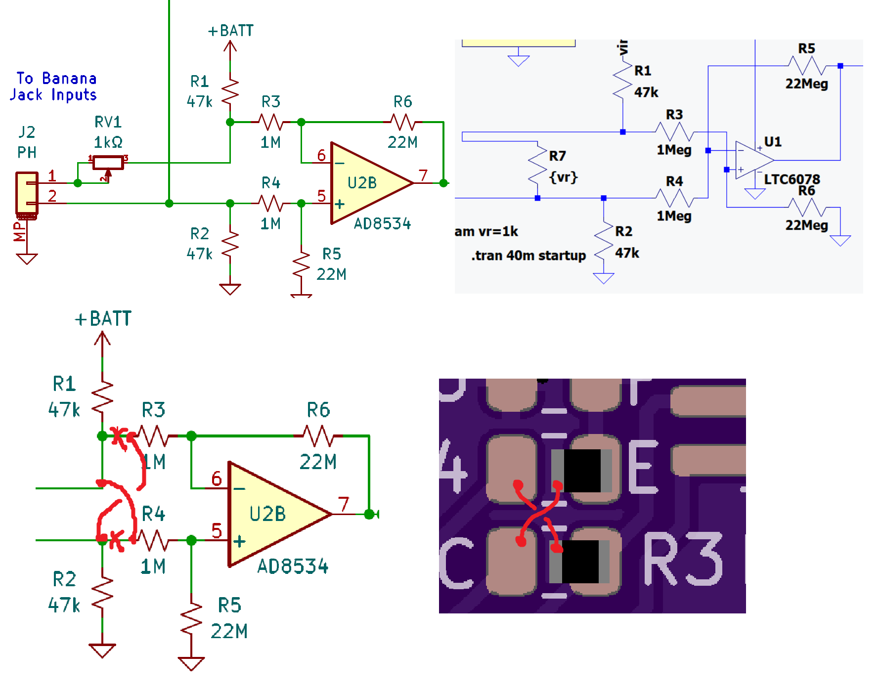
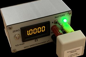
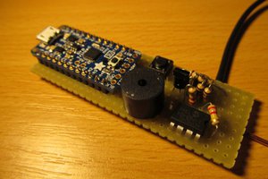
• Update April 25 2023

    John Guy04/25/2023 at 11:14 0 comments

    I just uploaded the correct schematic. I left the old one, it is from 2020, and is a very different topology. I might have had boards made, but I know I never built them.

    All the parts are here except AD8534, that should be a couple days. 

  • Possible Upgrade

    John Guy04/21/2023 at 17:54 0 comments

    I saw another idea here for a continuity tester which has much lower thresholds. As designed  it is hard to tell the difference between 0Ω and about 20Ω or so, rather this is optimized to measure 100Ω to 2kΩ or so.

    So, perhaps, a range switch to go 100x on the bias current, 40µA to 4mA. 

    I will be thinking on this ........

  • Status April 21 2023

    John Guy04/21/2023 at 17:49 0 comments

    Well, a casual glance at the tiny schematic icon of the project (used for now) and I think "Oh no! Did I cross the difference amplifier inputs? Sure enough I did. Below captures the schematic vs LTspice , and shows what is needed to fix this. Luckily these are all 0805 components so tombstoning a couple resistors and adding a couple bits of wire wrap wire (28g) is easy enough.

    In other news, boards are done in fab at OSHPark and on their way, as is the parts order from Digikey. The laser cut acrylic box should be here today or tomorrow.

  • Status

    John Guy04/19/2023 at 05:23 0 comments

    the parts are in the way from Digikey, the PCBs are in fab, and the box is cut and on its way

  • Parts

    John Guy04/18/2023 at 04:45 0 comments

    This cart at Digikey contains the parts to build one (with exceptions as follows)

    https://www.digikey.com/short/q0zz04jp

    The PCB itself can be ordered from Osh Park

    https://oshpark.com/shared_projects/pA0PM1oT

    The enclosure can be ordered from Lone Pine Laser

    https://www.etsy.com/shop/LonePinelaser

    One thing not in stock is JST PH cables, 2 pin, but these can be purchased from Adafruit

    https://www.adafruit.com/product/261

  • Enclosure

    John Guy04/18/2023 at 04:16 0 comments

    The enclosure was developed in Visio (I know, old school 2D CAD!) and output as SVG file. 

    First came the mockup:

    This mockup does not indicate any wall thickness, just the inside bottom area. I chose everything planar with a 15mm inside height, just enough to clear the bottom of the speaker, type CMS0361KLX by CUI.  There's also a pair of standard banana jack (one will be black of course), a Keystone # 2480 3x AAA Battery Holder, and the previously mentioned Beeper PCB, 40x25mm. 


    After some consideration I decided to make the enclosure out of 6mm transparent acrylic, and used the method called "Pettis Joint" or "T Slot Joint" or “Interlocking T-Bolt Construction”, at least according to this page. This method leverages the accurate planar cutting of a laser to drill what amounts to a sideways hole. I bought some M3 square nuts and M3 x 12mm flat head screws, and designed a joint around their dimension.

    In this piece you can see the top with a speaker grill, and the front end piece. The two square holes along the bottom edge of the top mate with the two square pegs extending up from the front piece. The screw is inserted through the top, and the square nut slides into, detailed below.


    In this view one is looking at the front edge of the enclosure, and the top has been connected and fastened.

    Once the design was all sorted out, I output the SVG file from Visio, and sent the files over to the people at Lone Pine Laser. Now we await the finished enclosure!

  • PCB Layout

    John Guy04/17/2023 at 23:05 0 comments

    The schematic capture and PCB layout were done with KiCAD, and PCBs are  in fab at OSHPark. They are 100% SMT, but should be easily hand assembled as the passives are all 0805, and the ICs are SOT23-5 and SOIC 14. 


    Inspecting the top of the PCB layout a few things should be noted. As this project was potentially to be built by others, I increased component spacing a bit to ensure every component had it reference designator nearby and unambiguous. 

    Also, note the 0805 components all have a letter next to them as well. If you look at the PCB bottom, there is a legend providing values or part numbers for every single component on the PCB. I wanted to ensure that if I or anyone else had a blank PCB in their hands it could be built without the aid of a schematic. I wish I did this more often!

    Beneath the op amp U2 AD8534 are the initials DFB, a good friend and the designer of the AD8534.

  • Detailed Design Explanation and Choices

    John Guy04/17/2023 at 22:46 0 comments

    The original circuit had some drawbacks, 

    1. It did not work well with 8Ω speakers
    2. It used a 9V battery (minor drawback, but I never really liked 9V batteries due to value)
    3. It used a now obsolete part
    4. I no longer have the complete schematic

    Many modern op amps are designed for 5.5V maximum, so three alkaline batteries AA or AAA will be great. The op amp needs the following characteristics:

    • Low IB, as one amplifier uses 1MΩ/22MΩ source and feedback resistance
    • High output drive current, as the op amp directly drives the 8Ω speaker
    • Bandwidth > 50kHz or so. I think it would be hard to fins one which meets criteria 1 and 2 but does not have this much bandwidth.

    Thus, a great fit for this application is an AD8534. This is a quad op amp, so all 4 amplifiers shown in the schematic are a single package. 

    One of the last elements added to the design is the LDO, an ADP122. This is a 300mA LDO, but why is an LDO needed? In this case, it does two things which quite different than expected. The first is that the LDO's EN input  is connected to the input probes. When the probes are open, resistor R2 pulls EN low, and the circuit is shut down. When connected to less than about 47kΩ impedance or less, the EN pin is pulled up to 1/3 of VBATT, or about 1.5V. The guaranteed logic high voltage for the ADP122 is 1.2V, so the circuit is turned on.

    The second thing which the ADP122 does in the circuit is provide a regulated voltage. This is only important for one element: the output volume level. The way the amplifier works the output volume is ratiometric to the supply voltage. Thus, when the batteries are new, the output could be adjusted to the desirable volume, but this would have to change as the battery voltage dropped over time. Volume is intended to be adjusted once with a trim pot, not frequently to accommodate the decaying battery voltage.

    Now back to the op amp part!

    Note the amplifiers are not U2A to U2D left to right. This is not how they started, but when the PCB was in floor planning stage U2B was closest to the inputs, so A and B were swapped. Then because A output feeds easiest to the top of the IC, amplifiers C and D were swapped as well.  Subtle, but worth mentioning to anyone just learning this stuff. The takeaway here is feel free to modify the schematic to make the layout easier.  If you are the person who did the schematic and are doing the layout this is easy. If someone else is doing the layout you may want to buy them a coffee or something due to the increase back and forth needed to do this. But a great layout engineer knows this already, and should ask you if it is OK if they do the swap.

    So, U2B is a simple difference amplifier. It measures the difference at the input probes and multiplies this by 22, and level shifts this to GND reference.  This is a classic op amp circuit we all should know! Resistors R1 and R2, 47kΩ, inject current into the probes. Note that R1 goes directly to the battery voltage, not the LDO output. Otherwise, the circuit would never turn on. I don't think I have ever made that particular mistake, but I am sure it has been done! The other thing to note here is the 1MΩ source impedance. I recall this as originally 100kΩ but it was increased. Resistors R1, R3, R7 and R8 form a path from battery to GND. Keeping these as high as possible reduces the standby current of the beeper box.

    Amplifier U2A is an integrator, another classic op amp circuit. Combined with U2D, a comparator with hysteresis, this becomes a classic VCO (Voltage Controlled Oscillator). This is explained as follows. Assume the difference amplifier is outputting 1V, the integrator output is at some high voltage, and FET Q1 is not on. U2A is an op amp just trying to do whatever it can to keep its inputs at the same voltage. In this case, IN+ is at 0.5V (1V divided by 2 due to R7 and R8). So the integrator needs to pull 0.5V / 100kΩ current through the feedback element,...

    Read more »

  • Status April 17th, 2023

    John Guy04/17/2023 at 18:37 0 comments

    This project has been years in the making, but never executed. When I saw the Hackaday Op Amp challenge, I knew I had to enter, and the Beeper Box was the perfect candidate.

    Right now, PCBs are out to fab, an enclosure needs to be cut, and I need to complete the Digikey parts order. I need to upload files, and shoot some video once the units are completed.

  • Beeper Box

    John Guy04/17/2023 at 18:33 0 comments

    Background

    When I changed jobs to be an electronic technician, I was given a schematic to build right away. It was titled "Beeper Box".  This task served a few purposes: a quick assessment of a newcomer's construction skills, an introduction to the tools and parts available in the lab, and also, it was an awesome tool to have. A beeper or continuity tester is quite useful, and nowadays this is a standard feature on a DMM (Digital Multi Meter) costing as low as $10 US. 

    So, why spend a few hours (or longer) building something that can be bought for the price of a good cheeseburger? The first reason is because this was a long time ago. In 1987, handheld DMMs were an exotic thing to have in a large lab. Sure, we had nice tool boxes full of what was needed, and a machine shop area too. But in 1987 DMMs were quite expensive, and also tended "to grow legs". That is, if left on a bench overnight, it was quite often not there the next day. One of the originals, the Fluke 8020A, was about $169 US when introduced in 1977. In today's dollars it is $863! Thus, although surrounded by a variety of bench multimeters all the way up to a few HP3456A flagship models, there were no handheld DMMs!

    Another reason why a beeper box was a good thing to have is it actually significantly better than the continuity function in a DMM. The way a DMM works, if the impedance is less than about 100Ω, the DMM emits a single tone chirp, usually around 1kHz to 2kHz from a piezo buzzer. But the beeper box is different. The beeper box injects some current into the test probes, and amplifies the resulting voltage. The amplified voltage modulates a VCO (Voltage Controlled Oscillator). Thus, the output frequency is a function of the probed impedance. In use, this provides significantly more information to the user. 

    USAGE

    When the beeper box is used on a blank PCB when checking for shorts and continuity it either beeps 200Hz or nothing. If a short is found where there should bean open, then using the analog capabilities of the beeper box is the best approach. For sake of explanation, let's assume a short from VDD to GND, both planes. To find this short, connect a power supply set to 0.5V and about 200mA current limit to VDD and GND. Connect the positive input of the beeper box to the VDD input, and use a probe on the negative. What happens is the tone increases as the probe moves towards the short circuit. So probing the various VDD pads on the PCB, the short is close to the pad with the highest frequency out of the beeper box. This is faster than using a DMM voltage readout because the user has to look from the PCB to the meter, and track mentally which reading was largest. it is much faster to use one's ear to determine highest frequency than to read a DMM.

    Once the PCB is populated with components the beeper box also is quite useful. A short is 200Hz, resistances up to about 3kHz cause a somewhat linear rise in frequency to about 2kHz. Capacitors above about 1µF cause a chirp, with the duration of the chirp proportional to the value of the capacitor.