 Mike
Mike
What the hell is this?
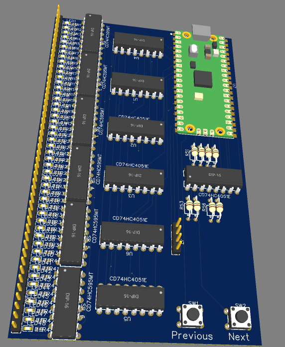
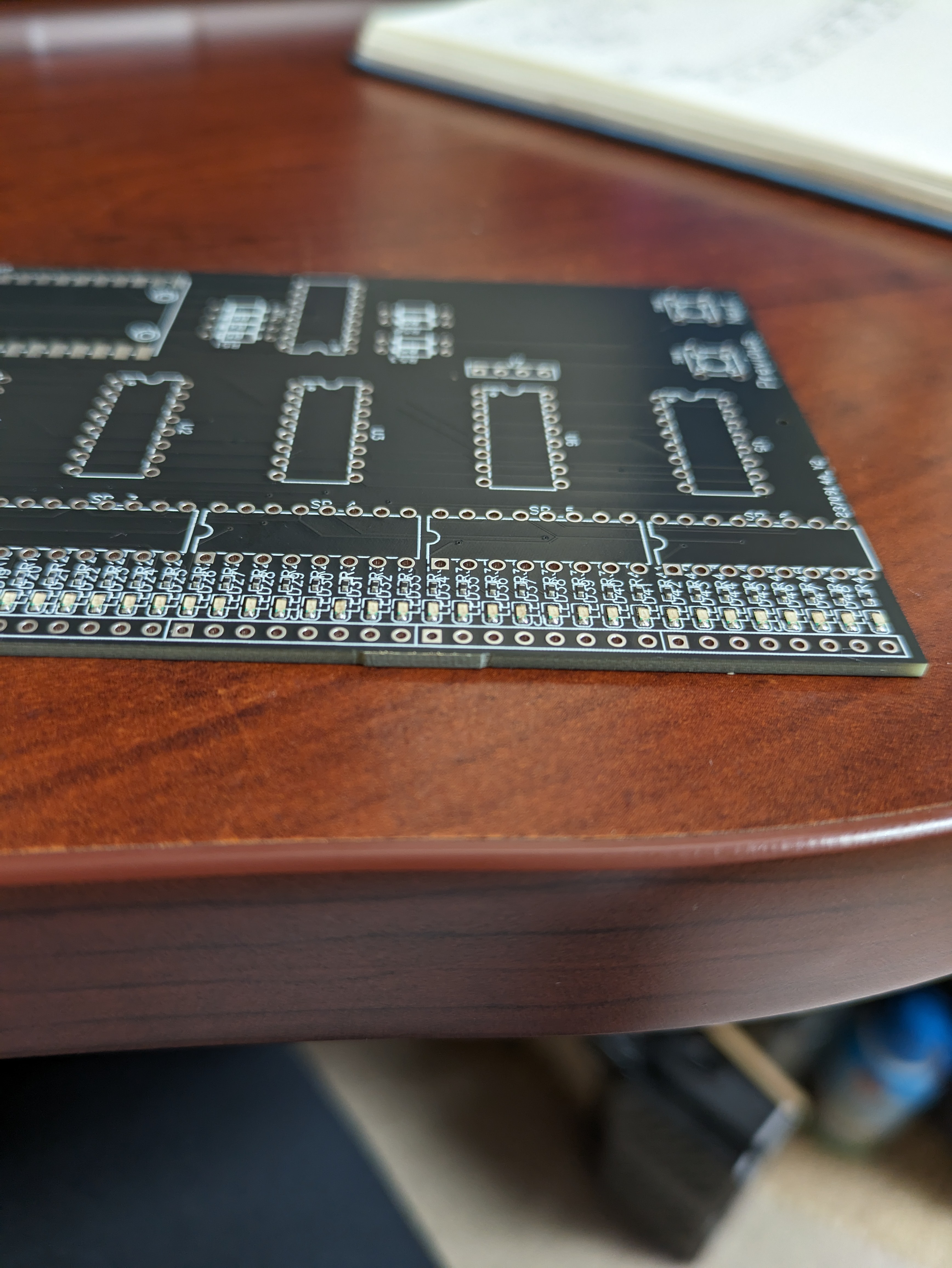
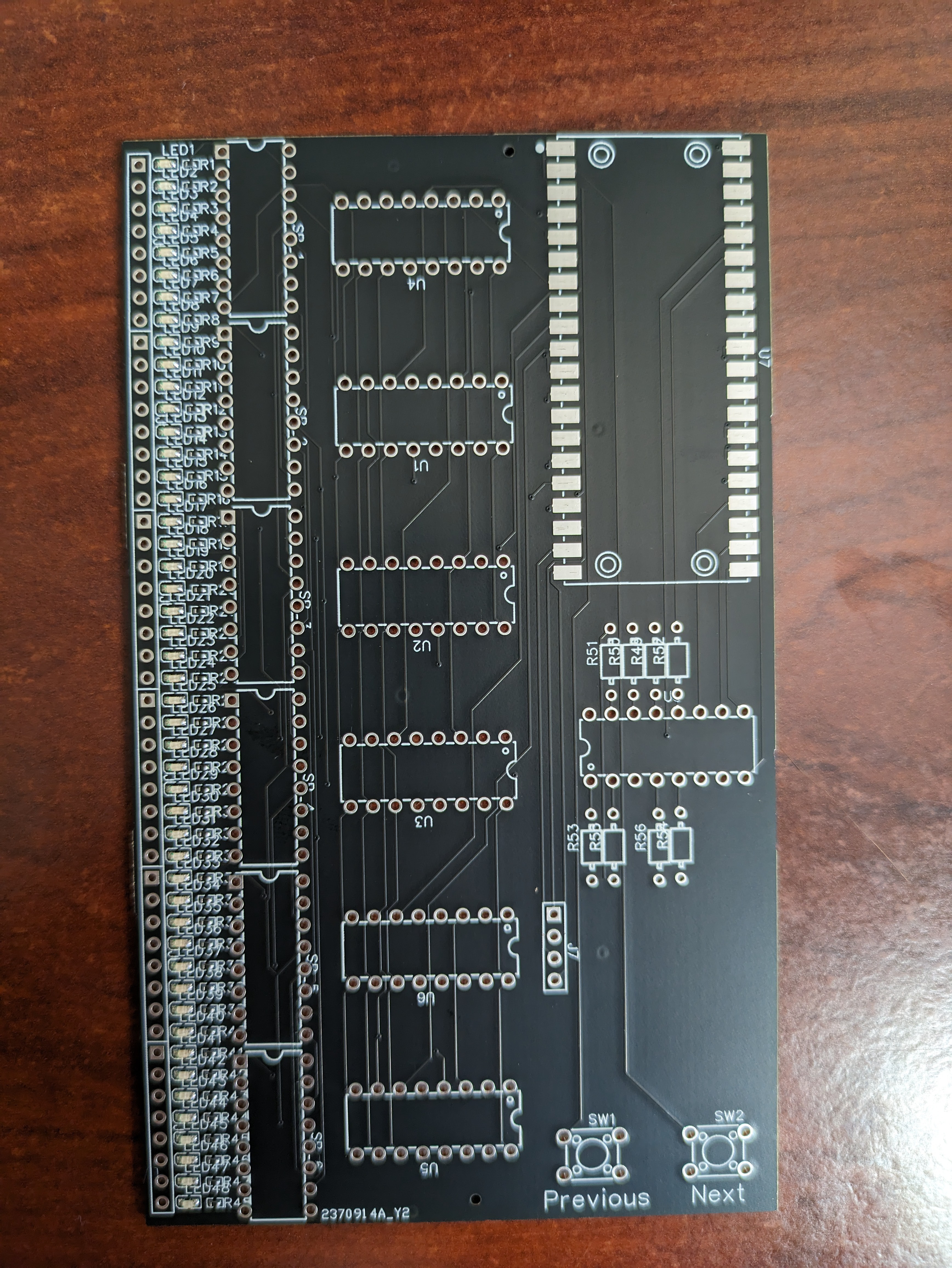
At a high level, the Resistorganizer is a PCB that you can plug into a standard solderless breadboard and it will poll the rows and determine the resistance value of the resistor which is plugged into it (across the DIP gap).
The board is driven by a RPi Pico, utilizing the ADC and some reference resistors to determine each resistor's value based on the voltage divider equation:
Where, in this case, the board is set up that all the resistors stored in the breadboard are R2.
So, that's all well and good, but without some automation, it would be easier to just check the values with a multimeter. Let's expand our ADC.
Shift Happens
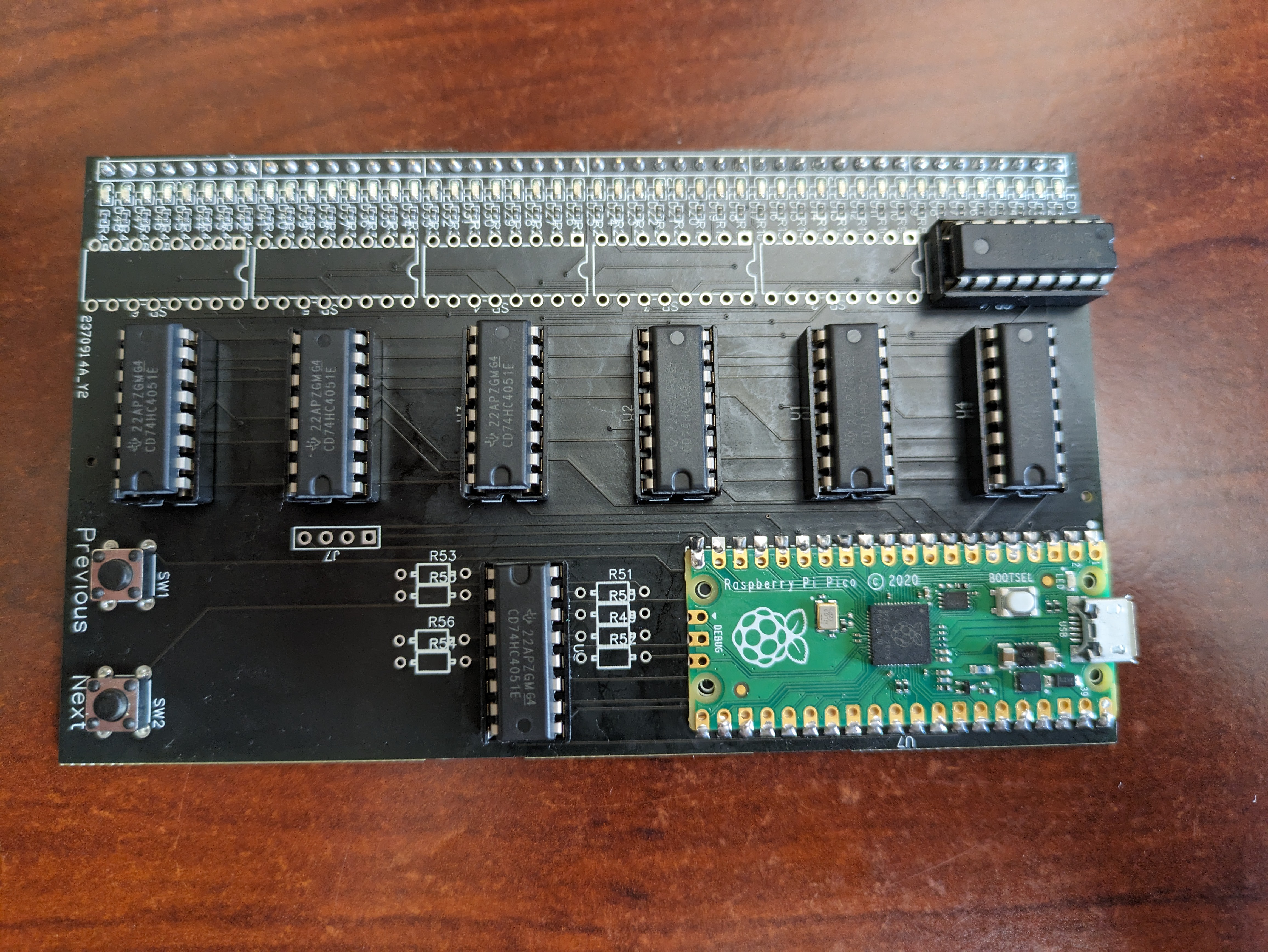
At the heart of this board is a handful of a cool IC, the CD74HC4051 analog multiplexer. This was a revelation to me that (of course) there's a chip out there that can act like a switch and multiplex an ADC. I'm inspired by this chip's bi-directionality. It should be noted that this chip has been replaced by TI with the MUX4051, a drop in replacement with better features.
Since this chip isn't going to be doing hard core signal switching, it's likely an overkill solution. But, if something needs to be killed, you might as well overkill it.
The 4051 has an 8:1 set-up, where you can poll 8 separate signals to the common terminal. Which channel is being polled is controlled with 3 address pins. The chip also has an enable pin, which effectively shuts the chip down. So, after the three address lines and the 'output' line, each chip only requires a single pin from your microcontroller to read up to 8 signals. Hell, you could throw another generic multiplexer to handle the chip enable pins and get a whole slew of ADC input for a total of... what is that... 3 address pins, 1 ADC, 1 Clock, 1 Latch, 1 serial... so 7 pins for up to a... crap-ton of ADC goodness. I think this is very cool.
Measuring Resistance Isn't that Straightforward... apparently.
Let's revisit the voltage divider equation again and take a look at an issue that arises from ADC precision (or lack thereof):
Vout / Vin = R2 / R1 + R2
In theory, it should be a trivial exercise in algebra to determine R2 if Vout, Vin and R1 are known. Sure. But, in reality, there are things to consider. The ADC is going to give you a value (in the case of the pico) between 0 and 4095 (12 bits). Where 0 = 0 volts and 4095 = ADCVref (3.3 v). Great, so if the reading is 2053 we can calculate Vout.
Yay. Based on the ratio of the max ADC value and the observed ADC value (~0.5) we can calculate that the resistance of R2 is very nearly equal to R1. Great. But, what if R1 is much, much higher or lower than R2? Well, looking at the equation at the top, as R2 gets much greater than R1, the ratio approaches 1 which would result in the output voltage being equal to the input voltage. The inverse is true as R2 is much smaller than R1, the ratio approaches zero and therefore the output voltage approaches zero.
I should have done some research on how a standard ohmmeter does this measurement. But I didn't. I want to roll my own solution. Here's what I came up with and it involves another CD74HC4051. (edit) I did some research and found out that ohmmeters commonly use a current sensor to determine the resistance. I have an ACS712 but a look at the datasheet makes me think that it won't be handling milliamp / microamp scale very well. So... back to the original idea.
The plan to mitigate this precision problem is to select 8 resistors for reference that will range from 220Ω to 2MΩ. These will be multiplexed as R1. So, for each R2 in the breadboard,...
Read more »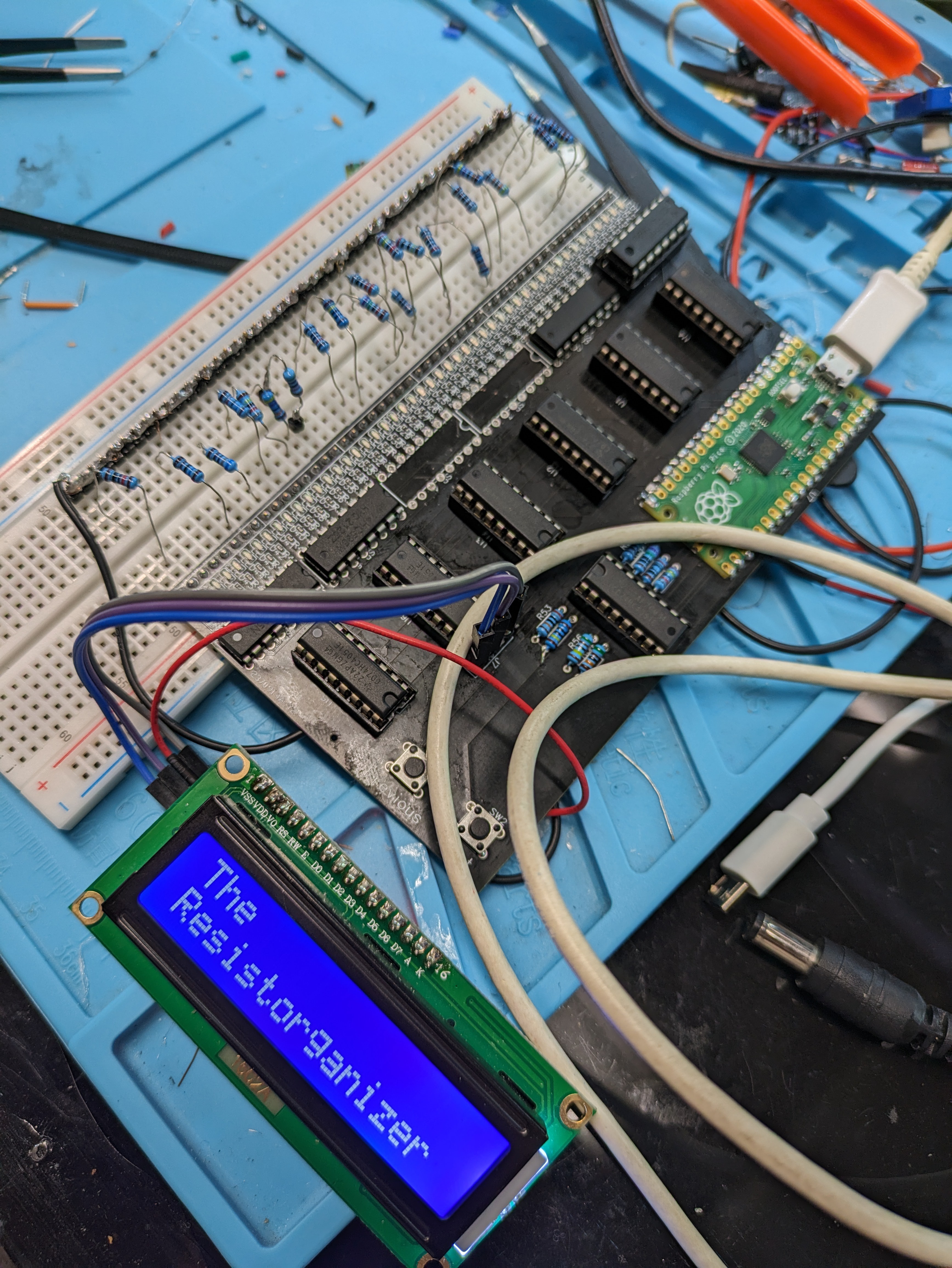


 jurc192
 agp.cooper
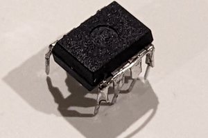
 Shranav Palakurthi
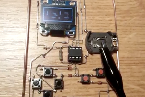
 davedarko
In fact, it's rare to actually require any resistor value to be more precise than 1 or 2 or 5 (1, 2.2, 4.7) plus a multiplier. I just sort my resistors into ten drawers by the third stripe.