Close
0%
0%

PicoPD - USB-C PD 3.0 PPS Trigger with RP2040

Adding Power Delivery 3.0 (PD3.0) & PPS to our beloved RP2040 chip in Pico footprint.

Similar projects worth following
Why can't we just utilize laying around USB-C wall plugs to prototype higher voltage devices?
How about unlocking 5A at 5V on your PD3.1 charger?

PicoPD will help you negotiate the voltage from your USB PD wall plug/power bank while still retaining the full functionality of RP2040. It will be a good candidate to USB-C PD your motor control board, controllable power supply, LED driver, custom battery charger, and more!

Also, just an AP33772 evaluation board

Purchase worldwide Elecrow - In stock

Purchase within the US/Canada Lectronz - Low stock

Buy It  


Documentation: 

Specification:

  • Power
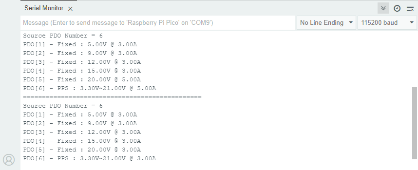
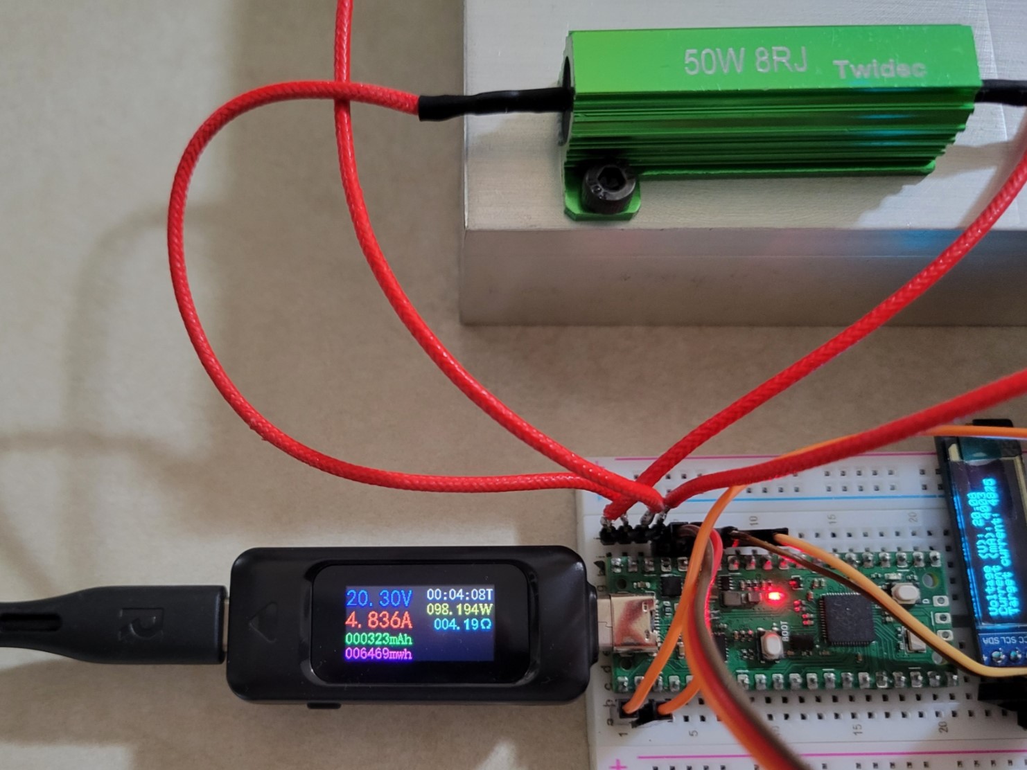
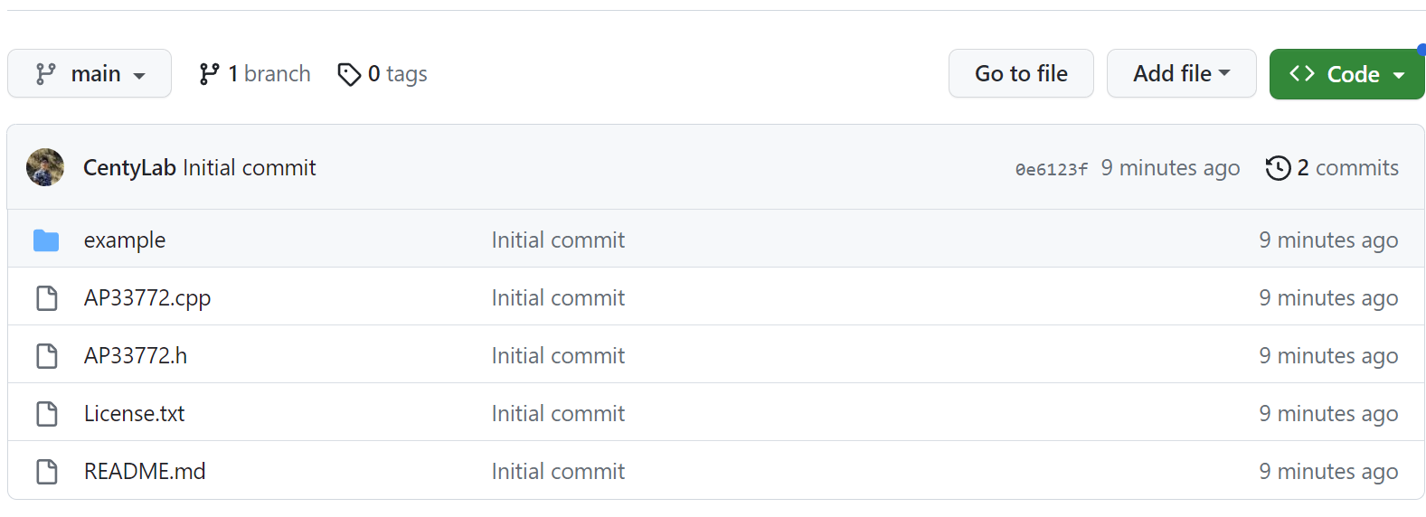
    • Capable of USB PD3.0 PPS provides 3.3V-21V output in 20mV step
    • Capable of USB PD2.0 Fixed Power of 5, 9, 12, 15, or 20 V at a maximum of 5A (100 W at 20 V)
    • +20A capable P-MOS load switch tied to USB-C VBUS
    • USB Type-C port (for power delivery and programming)
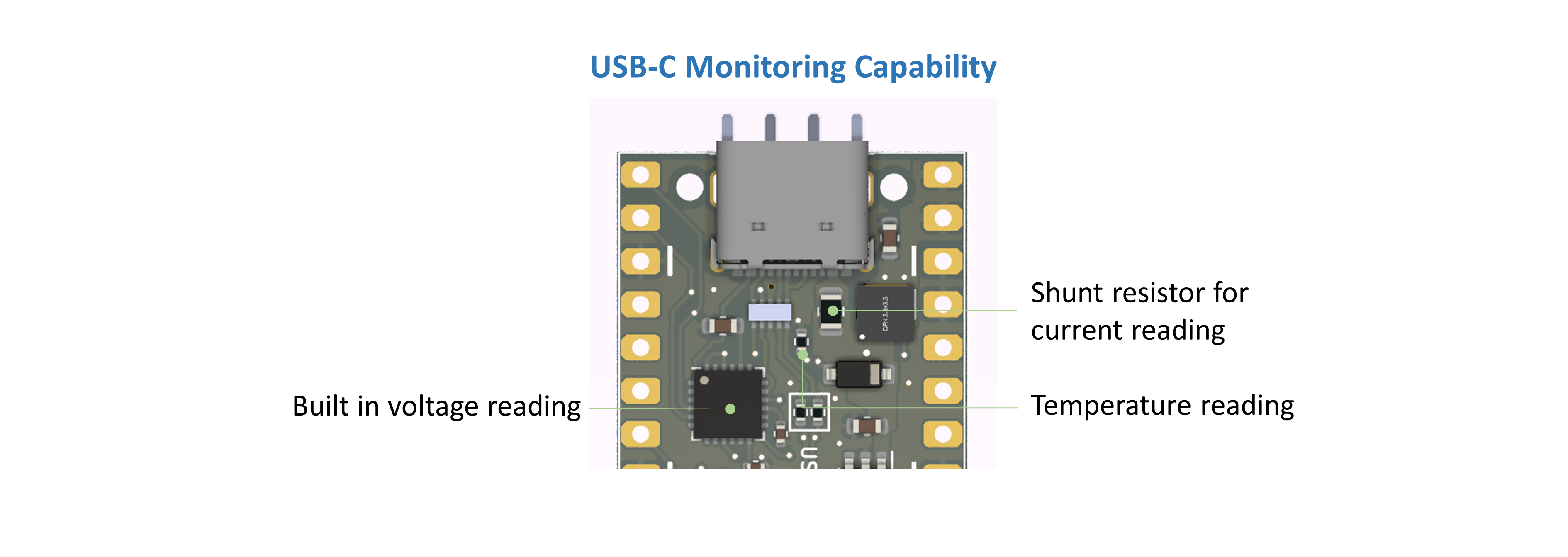
    • USB-C current/voltage reading build-in on circuit
    • ESD protection on D+/D-/CC1/CC2 pins
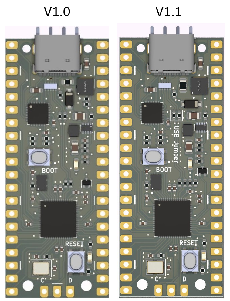
    • V1.2: 200mA LDO AP2204K-3.3 Low dropout
      • V1.0/V1.1:TPS62933 for efficient DC-DC converter for 3.3V @ 3A output
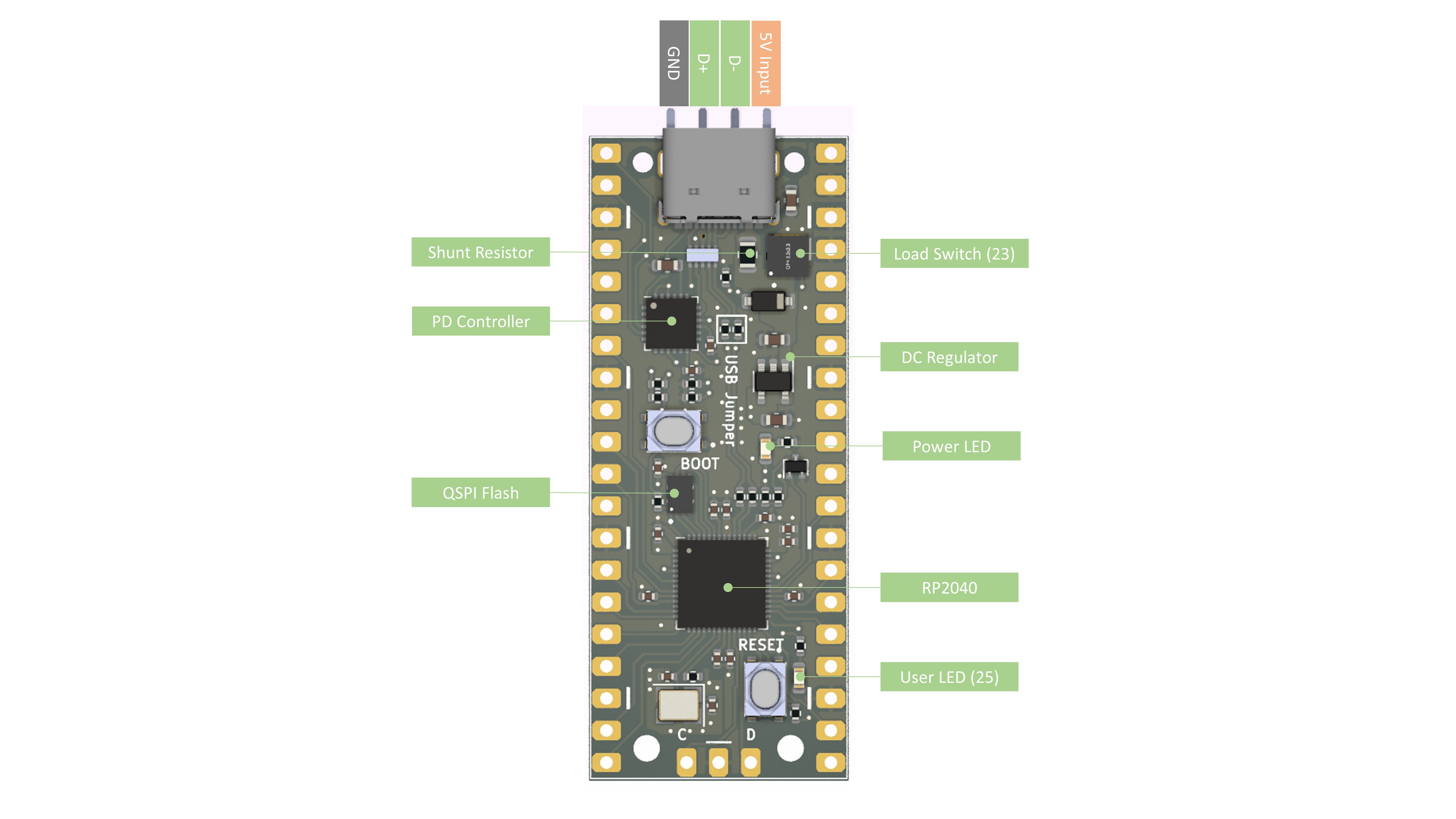
  • Microcontroller
    • RP2040 flexible clock running up to 133 MHz
    • 264kB on-chip SRAM
    • 16MB on-board QSPI flash
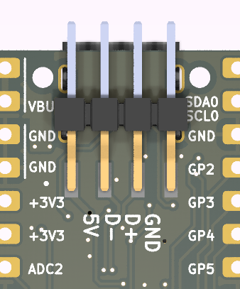
  • LEDs
    • Red - Power indicator
    • Green - User controllable - GPIO 25
  • Reset button
  • Boot button
  • Programming: Through USB-C, USB header, or SWD

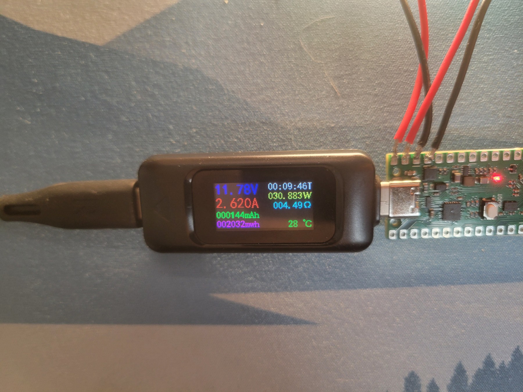
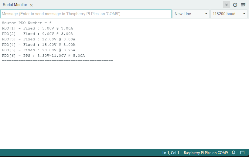
Changing voltage on the fly

Key player

The key player that enables the PD ability is the AP33772 IC from Diodes Incorporated. This is a relatively new IC that has an integrated USB PD controller with PPS capability. Power selection and power rail status checks can be done over I2C. All of the PD negotiation, refresh, and timing are done by the AP33772 IC. The microcontroller after making its power request in Setup(), is free to perform another task. This also simplified the code in comparison to the good old FUS302B which requires the microcontroller to do the heavy lifting.

The typical circuit utilizes a back-to-back NMOS configuration to create a bidirectional power switch. The switch remains open until the PD power negotiation is complete. My design omitted the NMOS switch so that the RP2040 can be powered as soon as the USB-C is plugged in.

Auto-detection for E-Mark (5A) and non-E-Mark (3A) cables using the same power supply.
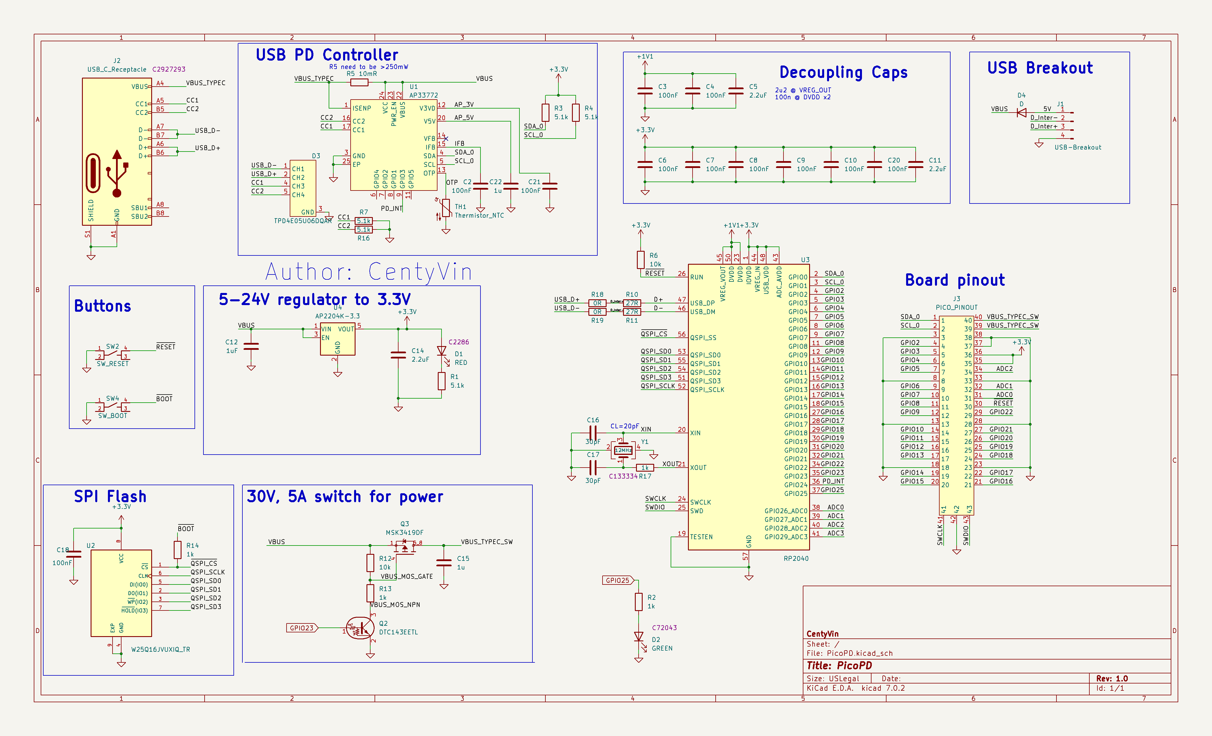
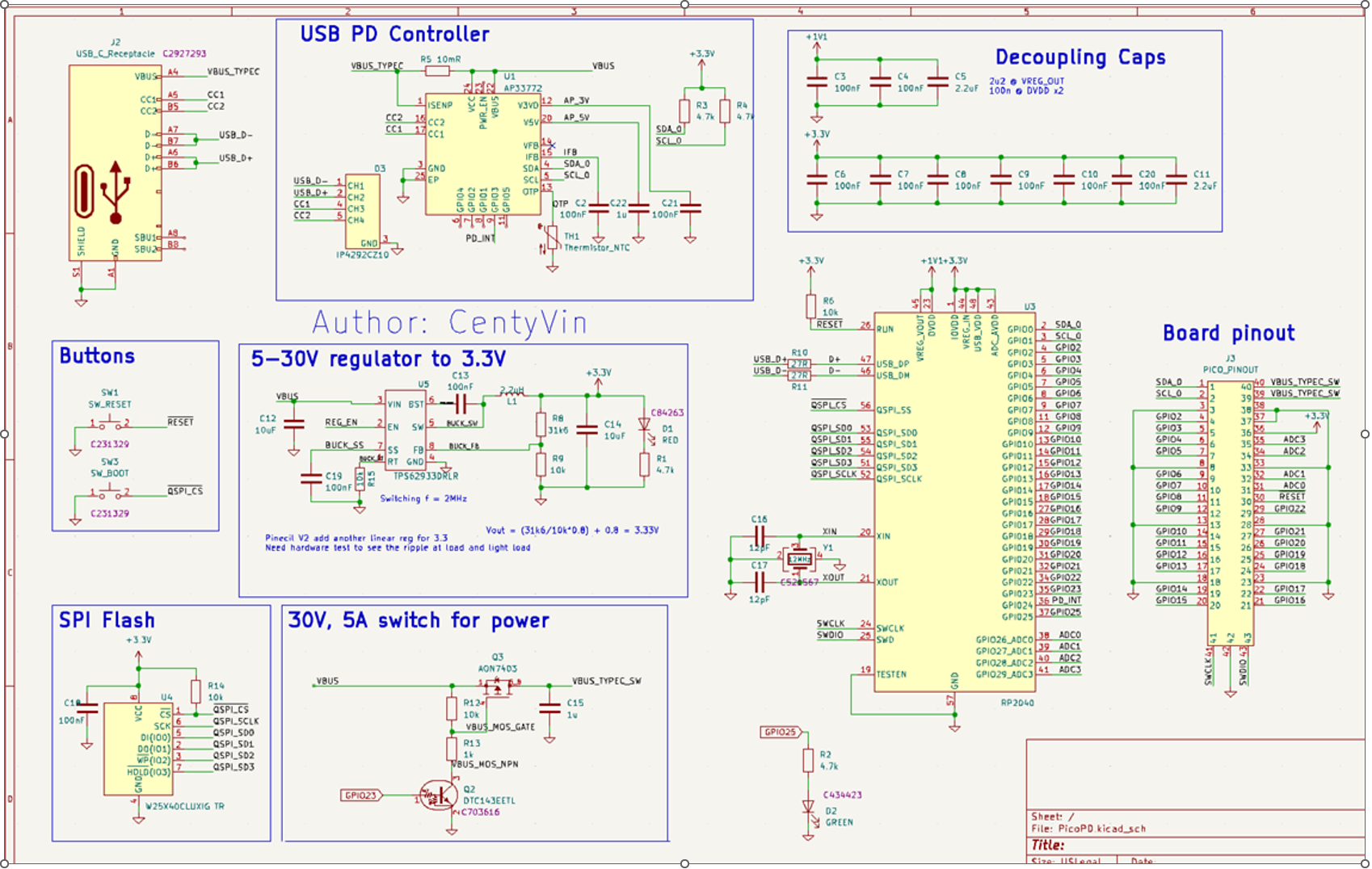
Circuit

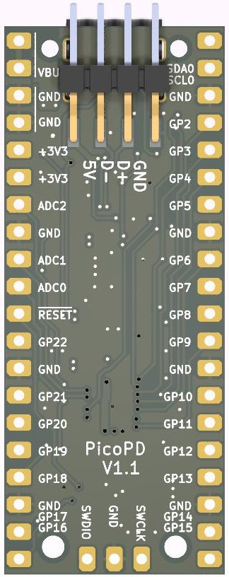
As we are designing a built-in USB PD/PPS pico board, we need all of the basic parts that make it a Pico.

  • RP2040 IC
  • Crystal Oscillator 12MHz
  • SPI flash
  • Supporting capacitors and resistors

But since we are going to have USB-C and higher power input than just 5V, we need higher voltage rating components and specialized IC:

  • USB-C PD controller: AP33772 IC
  • USB-C Receptacle 16 pins (USB 2.0 speed) 5A VBUS rated
  • ESD diode for CC1, CC2,D- and D+
  • DC-DC converter for 3.3V power rail
  • P channel MOSFET as a load switch

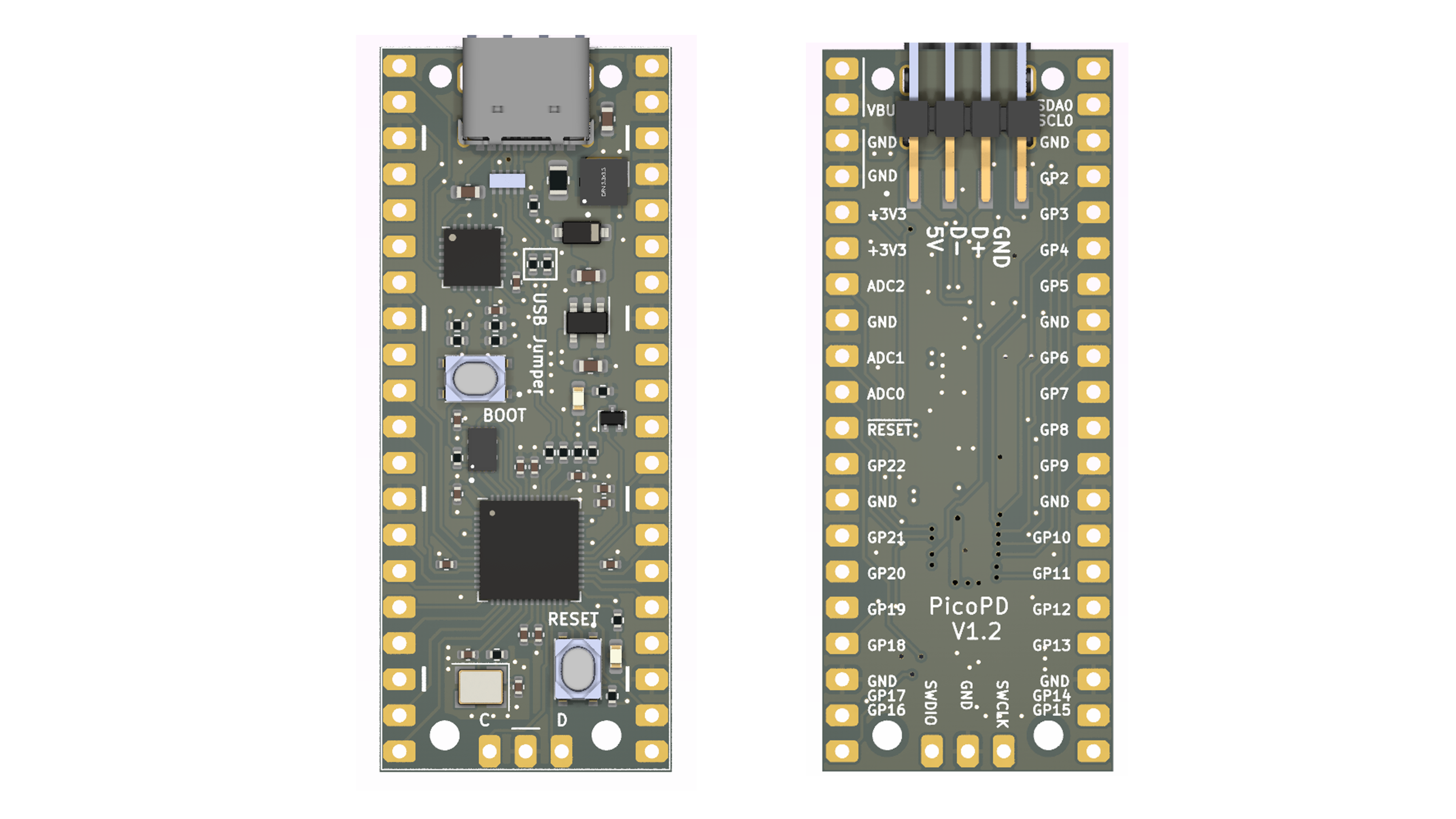
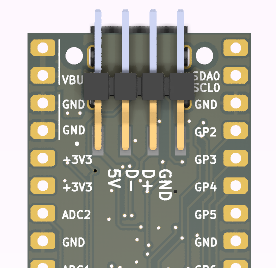
The RP2040 has 2x I2C hardware blocks I2C0 and I2C1. The USB-C PD controller will be connected to the I2C0 block at GPIO0 and GPIO1. Check the pinout for more details.


Testing Outcome

PicoPD Gerber V1.2.zip

Gerber files for PicoPD V1.2

x-zip-compressed - 163.85 kB - 12/12/2023 at 01:26

Download

PicoPD V1.2.step

3D model for PicoPD V1.2

step - 16.83 MB - 12/07/2023 at 08:44

Download

Schematic V1.2.pdf

Schematic for PicoPD V1.2

Adobe Portable Document Format - 210.27 kB - 12/07/2023 at 08:42

Preview
Download

Bill Of Material.csv

Bill of material with JLCPCB parts

Comma-Separated Values - 1.05 kB - 09/28/2023 at 06:54

Download

PicoPD Gerber V1.1.zip

Gerber files for PicoPD V1.1

x-zip-compressed - 166.44 kB - 09/28/2023 at 06:40

Download

View all 6 files

  • Update on AP33772 Library

    CentyLab03/13/2024 at 04:56 0 comments

    Originally, the PicoPD would require the user to unplug and replug in from the charger after uploading new firmware to request the power profile again. This mundane task can be annoying if you are actively adjusting a small part of the code.

    Thanks to Patrick, the AP33772 library can now request PDO profiles after a new firmware upload. Changes has been reflected to AP33772-Cpp Repo.

  • Enhance protection code for AP33772

    CentyLab02/03/2024 at 18:23 0 comments

    Attention: This feature will not work on PicoPD based on the design of the MOSFET

    The new code push for AP33772 now supports the built-in over-temperature protection and over-current protection. The over-temperature protection utilizes the NTC (negative temperature coefficient) component if populated. Remember to switch on the MASK flag to enable these features.

    • Fix voltage and PPS voltage request
    • Voltage reading
    • Current reading
    • NTC temperature reading
    • Set Over Current Threshold (if sense resistor is available)
    • Set Over Temperature Threshold
    • Set/clear mask bits

    To turn on over-temperature protection

    usbpd.setOTPTHR(100); //Turn off output if NTC detect 100C or above
    usbpd.setMask(OTP_EN); //Enable MASK

    PicoPD does not support over-current protection or over-temperature protection due to the design of the output MOSFET. In PicoPD, the MOSFET is controlled by the RP2040, and not the AP33772 IC.

    AP33772 IC does not support short-circuit protection. The datasheet does not mention this capability, and also no mention of over-current protection timing. I would not recommend using the AP3372 IC for high precision/high accuracy current-related sensing but as a rough estimate for current reading.

    GitHub: AP33772-CPP

  • Enable Serial debugging on PicoPD

    CentyLab01/13/2024 at 21:34 0 comments

    There are two ways to enable Serial debugging on PicoPD:

    Method 1: Using the provided solder pads at the back

    Step 1: Desolder the front "USB Jumper" resistors. They are just 2x 0Ohm resistors that bridge between the RP2040 IC and the USB-C port.

    Step 2: Use a USB Type A Plug Breakout Cable, or make your own from any USB cable and connect to the existing pad at the back of PicoPD

    Method 2: Use a USB-C Splitter that separates the USB 2.0 signal into another USB-C port. You only need USB 2.0 FullSpeed for the job, but never hurts to get extra speed if needed later. Some existing products:

    You then need a total of 3 USB-C Cables. If you are planning to pull 5A total, ensure your Power and Combined cables are both rated for 5A. The data line can be non-e-mark (3A)

    Method 3: Using a UART to USB Converter

    Tap on many RP2040 RX and TX lines. These pins can be configured within the setup().

  • Improve 3.3V Rail with V1.2 + AP33772 Lib Completed

    CentyLab11/30/2023 at 06:20 0 comments

    Changes with V1.2 PicoPD:

    • Replace buck TPS62933 with LDO AP2204K-3.3. This will drop the total output current from 3A to 200mA. However, we get a much cleaner and more accurate 3V3 line to 0.5% (DeltaVout/Vout). Our internal ADC will happily accept this stable voltage. Lower dropout voltage means requesting PPS as low as 3.5V before messing up your ADC read scaling. Fortunately, the LDO output will still be stable, just less than 3.3V if the input is below 3.5V. The previous buck converter design will be unstable when the input voltage drops below 4V, causing the system to reset.
    • Reduce component count.

    Update on AP33772 library:

    • Multiple users have tested the library and it seems to be stable.
    • The latest release has included setMask and clearMask functions

  • Refine PCB layout with V1.1

    CentyLab09/28/2023 at 06:53 0 comments

    Learning from the previous design, I have made some changes to the layout while keeping the schematic the same. Here are some main changes:

    • Highlight 0-ohm jumper resistor: To use the USB 2.0 header, remove these 2 jumpers. 
    • Highlight GND ports on the top layer
    • Thermal relief for the USB header: Easier to solder and desolder

    The next October 25th,2023 batch will be V1.1. You can make your own using the provided Gerber, else you can support me through Tindie PicoPD.


  • AP33772 Library Release

    CentyLab09/03/2023 at 08:59 0 comments

    I think the library is now at a point where you can use it for most of your applications. As of right now, it feature:

    • Fix voltage and PPS voltage request
    • Voltage reading
    • Current reading
    • NTC temperature reading
    • Set parameter for NTC

    Examples are included to cover most of the use cases that I can think of. Feel free to create an issue or comment here if you have any questions about your specific need.

    Still missing the ability to edit Mask which will be updated soon. The library also does not support interrupt mode so there will be no self-feedback from the IC. I look forward to further testing.

    GitHub - AP33772-Cpp

    Tested with:

  • AP33772 Library in progress

    CentyLab09/02/2023 at 00:32 0 comments

    I have been working on the AP33772 library. As of right now, I have most of the basic functionality satisfied like:

    • Set voltage
    • Set max current
    • Set warning/safety value
    • Read voltage
    • Read current

    With 140W Ugreen GaN charger - PPS

    With BaseUS GaN2 Pro - PPS

    With RavPower PD Pioneer 90W - Non-PPS

  • Second iteration - 1st batch order

    CentyLab08/30/2023 at 07:31 0 comments

    The 2nd iteration covers all the mistakes made in the previous one:

    •  5.1k Ohm termination on CC1 and CC2 to GND
    • QuadSPI flash
    • Crystal oscillator with 50Ohm ESR 
    • 1K series resistor to limit crystal oscillator drive
    • USB trace set to 90Ohm differential impedance

    Additional upgrade:

    • Breakout USB header to have extra D+/D- and 5V input
    • Blocking diode between 5V input and VBUS
    • Easier to press buttons


    Design challenges

    The initial design has USB D+/D- connected only to the USB-C. If using the USB-C only, the user has two options,

    • Connect to PC: programming and serial debugging, no USB PD.
    • Connect to USB brick: running existing code without the ability to flash or serial debug the code.

    All of this can be solved if you have an external flasher and debugger tool like Pico Probe using the SWD pins. Pico Probe works well with PlatformIO to compile and flash C++ code, but for MicroPython code using Throny, check out this method of packing your files into .uf2 and flash using PicoProbe. It is not as easy as just plug in your USB cable and flash it!

    What if we add extra header pins for the USB cable and a switch to select where the D+/D- comes from?

    The RP2040 has USB 2.0 hardware that is running at full speed. This means the fastest driver rise time is 4ns. FR4 propagation time is 6 inches/ns. We have a signal propagation distance of 24 inches over the 4ns rise time. If we are conservative and take 10% of the critical length, we have 2.4 inches of critical length that we can lose on impedance control. -> We have no problem losing impedance control over one 0 Ohm jumper 0402 resistor and one via.

    Now when adding the extra header, if not connected, we have a permanent trace stud on the D+/D- line. This stub can impact the signal by creating a reflection when the signal travels to the end of the stud and bounces back. Following this rule of thumb to calculate the max length of the stud and USB 2.0 Fullspeed @ 12Mbps, we have:

    maxStudLength (cm) = 0.75 / BitRate(Gbps) = 0.75 / 0.012(Gbps) = 62cm.

    62cm seems to be too long! However, if that is the case, we can have a permanent header sticking out at 1.4cm + (0.5cm for traces) without much of a reflection problem.

  • First iteration - 1st batch order

    CentyLab08/30/2023 at 06:55 0 comments

    Once the first batch of the first design arrived. I was quite excited to plug it in and hope the red LED will turn on indicating that there is 5V power going into the buck converter. But nothing lights up. I also wasn't able to flash the board and run blink. A bit of debug shows that I have made some rookie mistakes:

    • No 5.1k Ohm termination on CC1 and CC2 to GND
    • Order DualSPI flash instead of QuadSPI flash
    • SPI flash decoupling capacitor is placed too far away from the IC
    • Crystal Oscillator has 80Ohm ESR instead of 50Ohm ESR recommended by Rasberry Foundation
    • No series resistor to limit crystal drive
    • USB trace is not set to 90Ohm differential impedance

    Another Hackaday member also raised the question of how can you debug the board while providing PD power. With the current design, there are only two methods:

    • Use a USB-C Splitter to have CC1 and CC2 routed between PicoPD and power brick, and have D+/D- routed between PC and PicoPD
    • Use PicoProbe to program via SWD, and just plug the power brick directly into PicoPD

    The AP33772 IC also can perform a "hard reset" which will cut off the power to the PicoPD temporarily. If "hard reset" is in the code, the device can stuck at a boot loop. To prevent this, a separate power supply is needed if the sole purpose is debugging. 

    ---> 2nd design iteration is coming

View all 9 project logs

Enjoy this project?

Share

Discussions

Tuege Neumann wrote 03/05/2024 at 13:12 point

@CentyLab well done! This project looks great and is certainly something that is of interest to a lot of people. I have been dreaming of/working towards the same goal of a compact usb-c powered variable power supply since the 240W announcement was made. My approach eventually deviated from PPS all together for one simple reason. Many usb-c power supplies do not implement it and I wanted a solution that could be helpful to as many people as possible. USB standards are complicated enough and it seems counterintuitive to select your phone charger or power bank based on the trigger you will use it with. Especially since most people who want to use a trigger board already own their usb-c supplies. I eventually settled on a buck converter approach in order to make a single design more compatible with more power supplies. I am currently preparing the design of the buck converter stage for a world with 48V supplies while I wait for more capable usb-c sink controller ICs to finally hit the market. In case you're interested: https://oshwlab.com/tuege/main-pcb (not complete quite yet). I can see however how people with PPS supplies would tend towards a simpler trigger design such as this one so once again, well done and thanks for sharing your design!

  Are you sure? yes | no

CentyLab wrote 03/09/2024 at 23:06 point

Hi Tuege,

Thank you for your comment. PPS is not as hard to find as you might think as Anker and Ugreen are supporting it for most of their charger now. Your method would be a universal approach for all USB PD, also at a higher amperage. I am very interested in your implementation of voltage and current control.

My original goal is to have a whole prototype lab that can fit inside your backpack.  You have a USB-C soldering iron, hot plate, and now power supply. One other reason that I am going in this direction is the existence of some Chinese modules that have built-in voltage control, current control, and also a big screen. Analog is not my strong suit and it is hard to compete with those Chinese modules.

  Are you sure? yes | no

Patrick wrote 02/08/2024 at 00:24 point

Awesome project! It's perfect for something I'm working on, but was wondering if you have published the Kicad symbol and footprint anywhere?

I imagine I could mostly get away with using a generic Pi Pico footprint, but if there's significant changes anywhere it would be good to design my board with those in mind. Thanks!

  Are you sure? yes | no

CentyLab wrote 02/08/2024 at 01:57 point

Hi Patrick. It will work as it was designed with nearly exact dimensions and hole spacing as the Pico. It just doesn't have the castellated hole due to a major increase in cost. May I also ask what would be your application for this board?

  Are you sure? yes | no

Patrick wrote 02/08/2024 at 17:49 point

Thanks for the response! My project is a USB C cable/power supply tester, that I'm hoping to use both for testing USB PD support (hence the use of your board), and also testing which USB C pins are populated in the cables (using two other USB C ports). I'm designing the board so it can also potentially be usable as a USB C power supply in the future as well.


I was also wondering, do you have any of the version 1.1 boards left? I'm worried that all my indicator LEDs (the design currently has 24 of them) may approach the 200mA limit of the voltage regulator in the version 1.2 design. 

  Are you sure? yes | no

CentyLab wrote 02/08/2024 at 18:45 point

Hi Patrick,

Unfortunately, we don't have any packaged V1.1. Would it be possible to limit the current to your LED, maybe running them at 5mA each?

  Are you sure? yes | no

Patrick wrote 02/09/2024 at 04:40 point

Yeah, I can do that, I was just worried that might harm their visibility and/or make it more limiting for future uses of the board. I was thinking I might add a jumper to allow using VBUS instead of the regulated 3.3V for other components in case that becomes necessary. For my current project that'll be 5 volts, and not harmful to any other components, though of course that means I can't request higher PD voltages as needed. 

  Are you sure? yes | no

ManiSW wrote 01/14/2024 at 10:44 point

First at all, great project.

I've got some use cases i would use this hardware. What kind of PD source did you use for the serial example? I didnt get it working with serial AND power at the same time. With external powersupply i cant connect to PC (connector is pluged in the Power supply).

With connection to PC i didnt find a PD source wich would output power AND establish the serial connection.

Did you use different pins for serial?

  Are you sure? yes | no

CentyLab wrote 01/14/2024 at 20:11 point

Hi ManiSW,

Please check this one out: https://hackaday.io/project/192576/log/226908-enable-serial-debugging-on-picopd

  Are you sure? yes | no

ManiSW wrote 01/14/2024 at 21:50 point

Aah, i see. Second or splitter cable 👍 Thanks for the explanation.

  Are you sure? yes | no

Guus van der Sluijs wrote 01/11/2024 at 13:04 point

This is some impressive work. In the meantime the S variant of AP33772S has been released. Looking at the datasheet they are pin compatible. Can you see any major hurdles apart from updating the library to support the AVS functionality?

  Are you sure? yes | no

CentyLab wrote 01/12/2024 at 00:04 point

Hi Guus, we didn't even know the AP33772S existed. Thank you for letting us know. The structure of the register should be similar but we first need to get our hand on one of the chips to test it out.

  Are you sure? yes | no

CentyLab wrote 02/02/2024 at 18:15 point

Hi Guus. Seem like the IC is only available in large reels in Summer. Lead time is a bit crazy. We will keep an eye on it.

  Are you sure? yes | no

Guus van der Sluijs wrote 02/12/2024 at 09:27 point

Great! It's not so strange since PD3.1 power supplies are only just coming out. Looking forward to hearing from you again.

  Are you sure? yes | no

Finn K wrote 12/12/2023 at 05:01 point

Thanks for doing all this! Made implementing PD into my own project infinitely easier than I expected when setting out <3

  Are you sure? yes | no

corhen wrote 11/14/2023 at 01:27 point

This is a really cool project, and pretty close to what i want.  Two questions:

1) How hard would it be to use a potentiometer to change the request voltage?
2) can this handle a full 3 amps at the voltages?

  Are you sure? yes | no

Nick Cook wrote 11/16/2023 at 14:19 point

1) Wiring is as easy as using a ADC Pin on the PicoPD and then changing the programming to scale the potentiometer to the pps range (0-20V) you could use two pots and do both voltage and current. i am working on this now but am waiting on a small 1.3" screen to show values as i need a small variable supply for field tests and i may use an encoder instead of a pot.

2) Being Fully PD3.0 Compliant the PicoPD can run upto  20V/5A (100W)

I will post my project once it is complete.

  Are you sure? yes | no

CentyLab wrote 11/19/2023 at 16:55 point

Hi Corhen. Please check out this example project https://hackaday.io/page/21022-variable-power-supply-with-usb-c-pps-picopd

  Are you sure? yes | no

jacobsson wrote 11/07/2023 at 10:54 point

I'd love to see this in format as those small PD decoy modules you can buy!
I wonder in theory how small this could get if was pre-programmed for a fixed voltage.

  Are you sure? yes | no

CentyLab wrote 11/07/2023 at 18:33 point

That is a good challenge. I might have to make them one sided to save cost. Are you thinking of decoy with PPS? Small but programable?

For non PPS, Adafruit just release a board that you can set voltage with solder bridge. But pps allow you to pull 5A at "any voltage"

  Are you sure? yes | no

jacobsson wrote 11/19/2023 at 22:38 point

Yes, PPS would be sick in that format, even if it's a set voltage. This would change everything when it comes to wall chargers and old/new electronics! 

  Are you sure? yes | no

CentyLab wrote 11/19/2023 at 16:53 point

Hi Jacobsson,

FYI, I am making a small trigger board that do exactly what you said. Aim to release in 3 weeks. I will create a project page soon

  Are you sure? yes | no

jacobsson wrote 11/19/2023 at 22:34 point

Please notify me when it's due! I love this ❤️

  Are you sure? yes | no

CentyLab wrote 12/05/2023 at 19:51 point

@jacobsson I just created a new project. I am a bit busy with work but the prototype is working. Please find the project here https://hackaday.io/project/193933-ppstrigger-board

  Are you sure? yes | no

Nick Cook wrote 10/23/2023 at 14:27 point

Sounds good! Thank you

  Are you sure? yes | no

Nick Cook wrote 10/23/2023 at 11:30 point

Is there a possibility of supporting PD3.1 in a future revision?

  Are you sure? yes | no

CentyLab wrote 10/23/2023 at 13:07 point

We do have PD3.1 (up to 48V) development in the pipe line. The silicon is a bit more difficult to source so we might have to gauge demand, and might even do a group buy.

  Are you sure? yes | no

Nick Cook wrote 11/16/2023 at 20:08 point

i came across this chip it supports 3.1 and does not need alot of external components. i might do some design work if i get the time. HUSB238A

https://www.hynetek.com/uploadfiles/site/219/news/24322c00-2276-4d74-98db-c74432318210.pdf

  Are you sure? yes | no

CentyLab wrote 12/05/2023 at 19:52 point

@Nick Cook Hi, you have stumbled on the same IC as us. Same problem, we all need free time from daily job :(

  Are you sure? yes | no

Tuege Neumann wrote 03/05/2024 at 12:30 point

@CentyLab I am not sure whether the HUSB238A would really work for pd3.1 up to 48V. The issue that I keep finding with ICs is that while in theory they support pd3.1, they connect to VBUS to verify that the voltage is correct and these sense pins tend to have too low absolute maximum voltage ratings in order to use them for a proper 48V setup.

  Are you sure? yes | no

CentyLab wrote 03/10/2024 at 06:17 point

@Tuege Neumann, Oh you are right. HUSB238A only supports up to 28V. Also just no higher than a 28V charger yet.

  Are you sure? yes | no

Tuege Neumann wrote 03/10/2024 at 15:17 point

@CentyLab Good news though! I just investigated how the Framework 16 can offer charging up to 180W (with 240W charging being announced) and found out that they are using the CCG8DF IC by Infineon. Now this IC is theoretically also only rated up to 28V but one single line in the datasheet alludes to the fact that it can be used for higher power applications: "Note: Contact the Infineon local support team for application diagrams for any EPR designs with >= 28 V support." This is an option because this IC does not use a sense pin as previously mentioned and it does not need to be powered by the built in converter that is connected to VBUS. Instead it can be power through the VSYS power rail at 2.8 V to 5.5V which means that as long as there is an external converter that can handle the entire power range and provide either a 3.3V or 5V power rail (depending on your preference), the sink controller doesn't need to interfere with VBUS at all except through a load switch and therefore doesn't need to be rated for these higher voltages.

EDIT: Nevermind, unfortunately I just found out that the IC is only available on demand and is not stocked anywhere.

  Are you sure? yes | no

CentyLab wrote 03/11/2024 at 16:17 point

If you want to go the firmware way, there is a possible method right now. You can use a micro-controller that has built-in USB-PD CC PHY like CH32X035, then you can request anything without sensing the VBUS. If you want to check, you can always add a voltage divider or through another power control IC (current sensor ....)

  Are you sure? yes | no

Similar Projects

Does this project spark your interest?

Become a member to follow this project and never miss any updates