Close
0%
0%

Making Ted Yapos TritiLED

Documentation of the process and challenges along the way

Similar projects worth following
I'm building [@Ted Yapos](https://hackaday.io/ted.yapo) project [#Tritiled](https://hackaday.io/project/11864-tritiled).

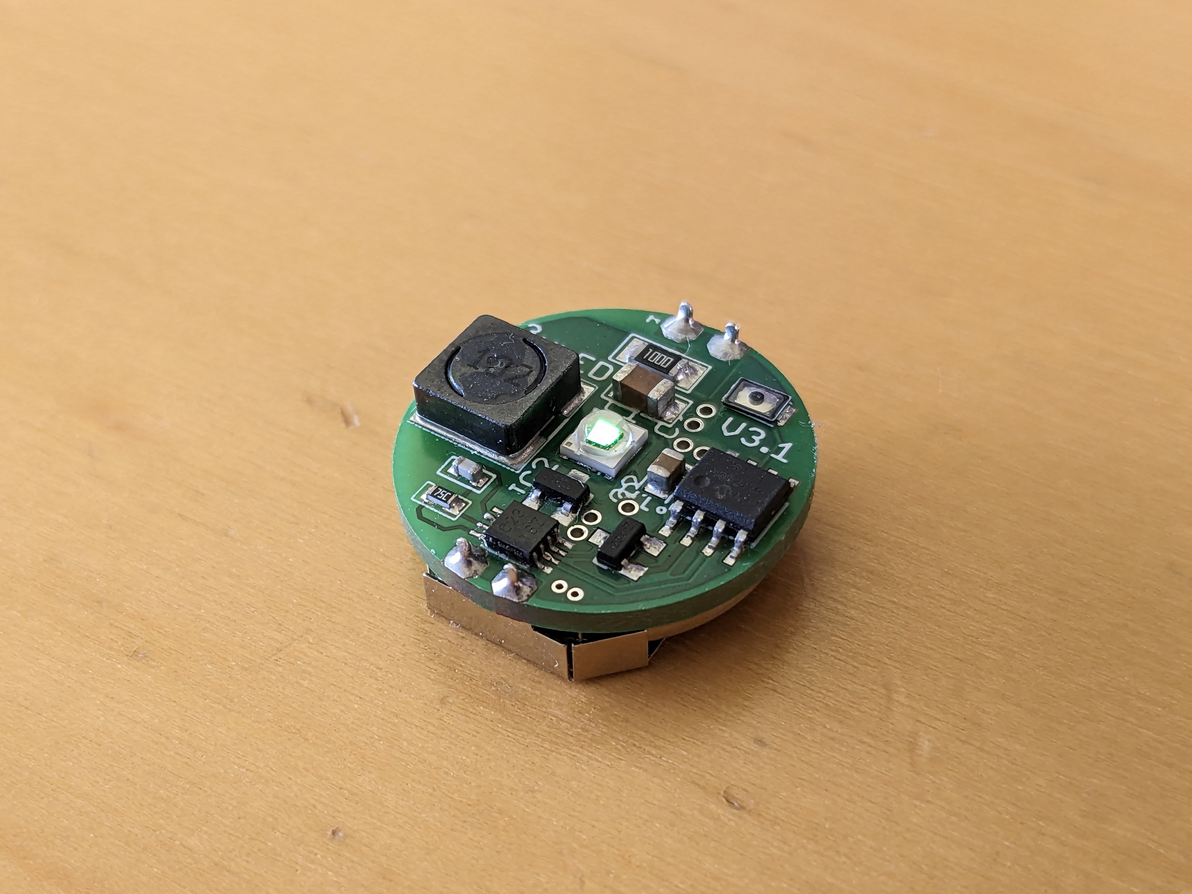
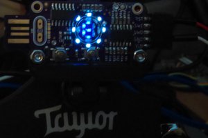
Since tritium light sources are hard to get in my country, I was looking for a more high-tech solution to finding my flashlight in the dark. Searching the internet, I found @Ted Yapo's project #TritiLED.

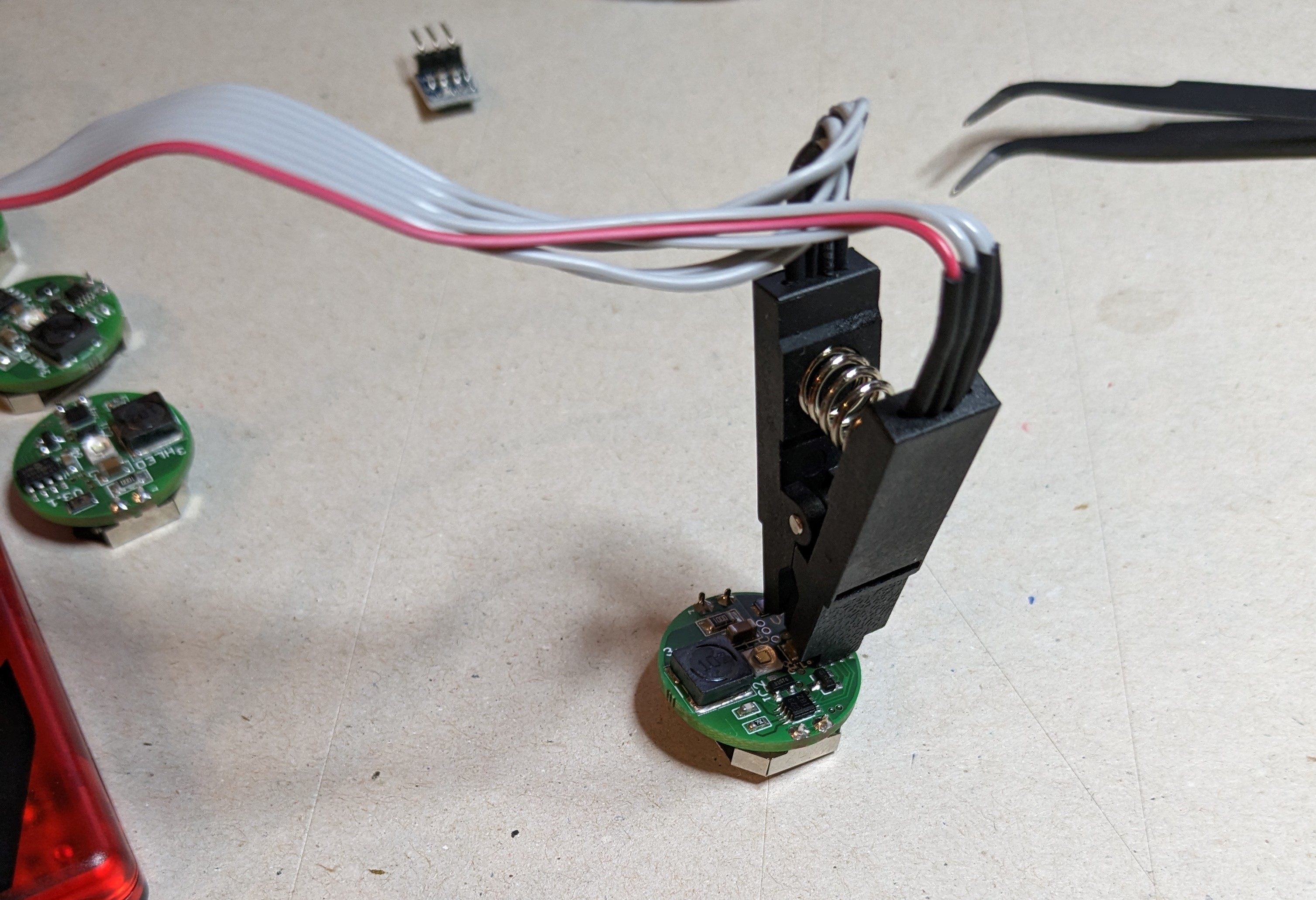
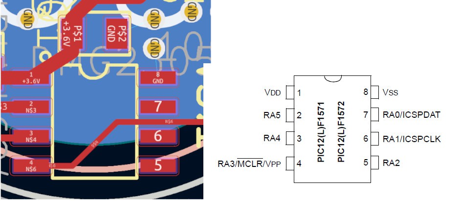
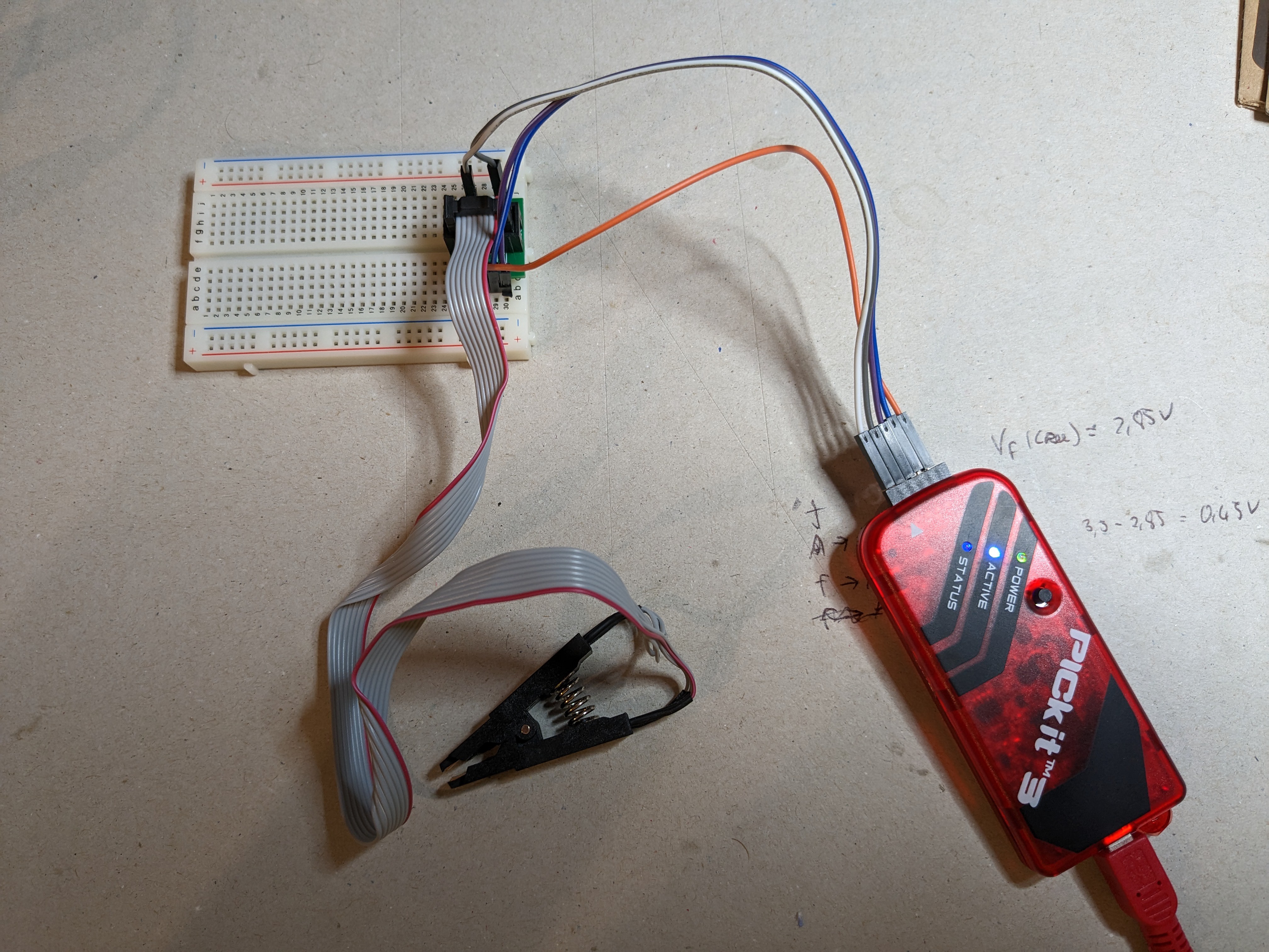
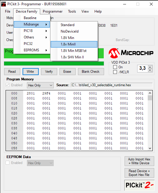
While his build logs are excellent, I was struggling with the more mundane aspects like programming a PIC microcontroller, and the required tool chain as well as SMD soldering. I'm writing about my learning process to document it for my future self and others that might have similar problems.

  • Closing remarks

    schlion06/04/2023 at 00:26 0 comments

    All in all, this was a kind of long wound but very rewarding project. I learned a bunch of new stuff and now have Ideas how I could do it even better next time.

    What I learned:

    • PIC ecosystem (software, programmers, tool chaines, a bit of history as well)
    • Using solder paste and SMD stencils
    • placing SMD componets
    • PCB reflowing with a hot pan (it is possible, and actually works quite well)
    • cleaning up flux residue

    Specifically, what I want to improve is:

    • try out hot air rework stations, possibly get one
    • get brushes or other better tools for cleaning up flux residue / possibly even get better flux
    • ...

    What remains:

    • finish up this write-up
    • put them into small waterproof containers
    • possibly fork the git repository and push additions to calibration.py
    • possibly try making a nicer silk screen with markings for the LED polarity (might require EAGLE :/) as not to mess with Ted's original files

    Some pictures of my finished fleet:

  • Calibrating: Much confusion and reworking in a hot pan

    schlion06/04/2023 at 00:25 0 comments

    So now I had 6 TritiLEDs and was ready to calibrate them using the procedure described in Ted's corresponding build log. I applied the programming clip, uploaded the calibrator.hex file and measured the current.

    Here's my janky way of powering things, The vias (through holes) are connected to GND, that's why this worked, you can see it in the board view:

    But instead of the 10.3, 19.4 and 37.7 µA @ 100, 200 and 400 Hz, I was getting more in the order of 94, 184 and 344 µA. At hat point I got stuck. I tried the other boards, but the power consumption was similar. I had noticed that the interactive BOM, I had generated from Ted's EAGLE file had a 100nF decoupling capacitor (C2) instead of a 1µF one. So, I tried switching it out and ended up breaking the capacitor because I did not manage to heat both side enough to desolder them at the same time. But instead of changing out C2 I exchanged C3, the enegry-storing 10µF capacitor. And this did lower the current, but not enough. I would still need to drive the LED at well below 50Hz to even get to a year. This, of course, means a blinking LED rather than a dimly glowing on. So, I commented on the Calibration log and slept on it. The next day, Ted himself answered and suggested that I probably mounted my LED the wrong way, driving it directly when the monostable was on and not powering it via the inductor. This also explained the better performance without the 10 uF capacitor.

    So it was hot sand pan time again! I de-soldered the battery clip, heated up my sand, put some flux around the LED, waited for the solder to melt and turned the LED around 180°. This was pretty difficult working over a hot pan without magnification. On two PCBs, I didn't get it quite right and had to reflow them again, but in the end, all of my 6 TritiLED were working as expected, consuming around 13, 25 and 49 µA. After that I used up the rest of my components to make the remaining 5 tritiLEDs, this time doing everything right from the start. Here are the final currents draws for the XPE2 LED:

    Hz 1 2 3 4 5 6 7 8 9 10 11 mean std
    100 13.70 13.60 11.40 13.40 12.80 13.90 12.40 13.75 14.7 12.6 12.6 13.17 0.91
    200 26.20 25.80 21.70 25.40 24.30 26.70 23.70 26.20 28.1 24.1 23.95 25.10 1.8
    300 50.90 50.30 42.10 49.40 47.40 52.00 46.10 51 54.8 47.1 46.65 48.89 3.5

    I then put all the currents in the currents.dat file, ran the calibrator with

    python .\calibrate.py

     and compiled everything with

    & "C:\Program Files\Microchip\MPLABX\v6.10\gnuBins\GnuWin32\bin\make.exe" tritiled_v30_selectable_runtime

    Then I tested the every one of them to see if they were working properly. For one of the PCBs, I had to reflash it.

    At last comes the cleanup, of both my workbench, but also all the flux residue.I used 99% isopropyl alcohol and cotton swabs. But found out that holding a small piece of tissue with my tweezers was much more suitable for getting into narrow channels around the LED. I've also seen people use paint brushes. I should get some of those.

  • SMD soldering II: bring the heat!

    schlion06/04/2023 at 00:17 0 comments

    I had solder pasted and populated a whole PCB, and now it was time to cook!  Equipped with an infrared thermometer, some playground sand, an old pot and some aluminum foil, I was ready to rumble. Before using the sand, I had sifted out lager particles, washed it and dried it in the oven at max temp, sanitizing it in the process. I added about 0.5 cm of the sand and slowly heated it up. Sand insulates relatively well but also has a decent heat capacity, so it takes some time. Be careful that the bottom of your pot doesn't get too hot, while the top is still cold. My solder paste is supposed to melt at 189 °C, so I waited until the surface of the sand was at about ~200 °C and lifted the PCB in on a bit of aluminum foil.

    Note: This is a later batch, the 6 original units were all baked while still held together by the surrounding PCB.

    With all of these black parts, you can actually get an okaish reading from the PCB itself (if you are unfamiliar with the concept of emissivity, you should check it out, it's quite fascinating. In short: shinier objects reflect more light, so the sensor gets confused because it sees the reflection of e.g. the ceiling. To get the best possible reading you need a non-reflective black surface. Sand actually performs reasonably well). Most importantly, I watched for the solder to become shiny everywhere and then left it in for an extra 20 seconds for good measure. All of this worked surprisingly well.

  • SMD soldering I: Preparation

    schlion06/03/2023 at 23:33 0 comments

    Before this project, I had never done SMD soldering, maybe bodging a wire onto an ESP8266 ESP-01 module, but that was it. Usually, I'd just try to solder all the tiny components by hand. But the LED that we're using doesn't have contacts on its side, but rather the solder pads are under the chip :/


    This calls for a different soldering technique and a learning experience! There are quite a few ways of soldering PCBS from fancy vapor phase soldering, over IR and convention ovens (industrial and DIY), to hot air rework stations and finally the humble hot plate. I did not find a lot of recent articles about reflowing and since my maker space doesn't have a reflow oven and I don't have a rework station, I tried the hot pan/ hot plate reflow technique (https://www.sparkfun.com/tutorials/59), since it was cheap and the former tenants left me with an abundance of old pots.

    For applying the solder paste, I also referred to a Sparkfun blog post. Although I did change it up a bit. I only extruded a small amount of paste from the syringe and wiped it over the stencil with a credit card.

    Then I started populating the PCBs using tweezers. What really helped me was an interactive Bill of materials. It really helped me keep track of what I had already placed and where. And it's just a simple HTML file.

    I generated it with the KiCAD Plugin: Interactive HTML BOM, but you can use it in standalone mode, even with EAGLE files. You might need to install some python packages first

    pip install wxpython jsonschema

    And then you can run

    python ./<path>/generate_interactive_bom.py ./tritiled/hardware/eagle/V3/tritiled_v31_xpe.brd

    PCB with solder paste and some components.n In the end, I should have tried just making one of these and learn from that, but hindsight is 20/20.

    With (ceramic) capacitors and resistors the orientation doesn't matter, but for the LED, and the monostable vibrator and the PIC it really does! The PIC is easy, as there is a dot marking pin 1 and also a dot on the PCB. I double-checked the datasheet anyway and compared it with the board view, after importing the board to KICAD.


    Note: Microchip calls Vcc Vdd and GND Vss.

    Same for the monostable. The PIN 1 marker is a grey bar in this case.

    And at last the LED.

    At this point I made a mistake. I put the Anode of the LED to the 3.6V pad. In that moment I had forgotten, that the LED is supposed to act as a flyback diode. That's the whole point! Had I checked the schematic I might have avoid making this mistake six times in a row.

  • Programming PIC

    schlion06/03/2023 at 22:42 0 comments

    This was my first time using PIC microcontrollers, before I had only used Arduinios and Atmels (programmed via Arduinos). I did not realize I would have to buy into a whole new µC universe. The first step was getting a programmer. I got a PICkit3 clone on ebay for about ~35€. I should probably have gotten something else, especially since Microchip acquired Atmel in 2016 their newer programmers also support Atmel chips (nice!). Getting a genuine and supported programmer is nice, since there is documentation, and you can be relatively sure that the problems one experiences are a result of a user error and not so much your programmer or software being flaky. Buuuut, since the reasonably priced MPLAB SNAP was out of stock and most of the other options were much more expensive, I stuck with the clone.

    As soon as I had the programmer I realized I had no way to connect it to the PIC @Robert had the same question and @Ted Yapo suggested the use of a SOIC-8 Clip. So I got one.


    The next problem was the tool chain. The newest version of the Microchip IDE and the corresponding programming software MPLAB IPE, do not support PICkit3. Luckily [PICkitminus](http://kair.us/projects/pickitminus/) exists. I was able to recognize my programmer. Connecting the clip to a bare PIC and setting the correct device family, I tried connecting to the PIC, but although I could read from the device, I could not write to it.

    I tried activating the VDD, but it didn't work. What did solve my problem was just using an external 3.3V power supply. I actually used an ams1117 3.3v board and a USB brake -out board to get 3.3 V from my PC's USB.

    Really handy, you should get some. Now I could finally program the PIC!

    So now that we can write .hex files to the IC, I would like to generate them as well. Luckily, there is a makefile in the repository. For it to work, we need some kind of make utility and a compiler.  I got my make from the MPLAB X IDE, since windows doesn't have make natively. The compiler is not bundeled with the IDE, so I downloaded the MPLAB XC8 Compiler (it's the one used for 8-bit Microchip microcontrollers). Setting up a whole project in MPLAB seemed very tedious and complicated, so I just ran:

    & "C:\Program Files\Microchip\MPLABX\v6.10\gnuBins\GnuWin32\bin\make.exe" tritiled_v30_selectable_runtime

     in the /tritiled/software/tritiled30/src folder. Additionally, I had to set the path to the compiler in the makefile:

    XC8 = /opt/microchip/xc8/v1.34/bin/xc8
    to
    XC8 = "C:\Program Files\Microchip\xc8\v2.41\bin\xc8.exe"

     or wherever else your compiler is. Then I was set up to follow the procedure described in https://hackaday.io/project/11864-tritiled/log/82040-v3x-calibration-procedure/.

  • Ordering Parts

    schlion06/03/2023 at 21:58 0 comments

    I ordered the parts for the 3.1 XPE2 version in September 2021 in July 2022 the last part finally arrived. I intended to make 10 TritiLEDs, so I ordered 11 of every components and some extra of the cheap ones like resistors and capacitors. I ordered the PCB and the stencil from a local PCB shop. I ordered the PCB three times, since it was the minimum amount. An electronics shop nearby was closing down, so I used the opportunity to get some solder paste and say goodbye. Now finally I have everything I need!

View all 6 project logs

Enjoy this project?

Share

Discussions

Similar Projects

Does this project spark your interest?

Become a member to follow this project and never miss any updates